Sign In
Upload
Manuals
Brands
Texas Instruments Manuals
Desktop
990
Texas Instruments 990 Manuals
Manuals and User Guides for Texas Instruments 990. We have
9
Texas Instruments 990 manuals available for free PDF download: Operation Manual, User Manual, Manual, Installation And Operation Manual, Maintenance Manual, Installation Manual
Texas Instruments 990 Operation Manual (276 pages)
Prototyping System
Brand:
Texas Instruments
| Category:
Desktop
| Size: 22.35 MB
Table of Contents
Table of Contents
5
Introduction
11
Purpose and Capabilities of the System
11
Prototyping System Software Description
11
Hardware Configuration Required for System Software
12
Section L General Description
11
Software Modules
15
General
16
Debug Monitor (PX9MTP)
19
Monitor Overlay Functions
20
User Area System Programs
22
System Part Numbers 1"5
15
Prototyping Process
23
Section II. System Installation and Operation
25
Entering Commands on the Terminal Keyboard
25
Input/Output and Logical Unit Assignments
25
Introduction
25
Operating the Monitor
25
Unpacking and Installation of Hardware
25
Using the 733 ASR ROM Loader
25
Loading and Executing Programs
32
Loading
33
User Program Interface with System Software
33
Executing a User Program
33
Interrupts and Single Instruction Execution
34
Interrupts
34
Protect Violation Flag
35
Protecting the Monitor
37
General Description
39
Input/Output Operations
41
Methods for Loading Programs
41
Introduction
39
Debug Functions
41
Debugging Modes
42
Assign LUND (AL)
43
Comparison of Debugging Modes
43
General
43
Keyboard Commands
43
Load Program (LP)
43
Summary
43
Execute User Program Directly (EX)
44
Execute User Program under SIB or Trace (RV)
44
Link and Load Program (LL)
44
Load Overlay (OY)
44
Load PROM Programmer (PL)
44
Modify Registers (MR)
72
Inspect Registers (IR)
73
Inspect Workspace Registers (IW)
74
Modify Workspace Registers (MW)
74
Modify CRU Register (MC)
75
Inspect CRU Input Lines (IC)
77
Set Snapshot (SS)
78
Inspect Snapshot (IS)
79
Clear Snapshot (CS)
81
Set Breakpoint (SB)
82
Clear Breakpoint (CB)
83
Clear Trace Region (CR)
91
Find Byte (FB)
92
Find Word (FW)
94
Set Write Protect Region (SP)
96
Clear Write Protect Region (CP)
97
General Description
113
Introduction
113
Loading and Initialization Procedures for the Text Editor
114
Starting Execution
114
Final Message
115
Text Editing Procedures
115
Movement of Pointer
115
Commands
119
Setup Commands
120
Edit Commands
122
Output Commands
126
Messages
127
Error Messages
127
Warning Messages
128
Source Program Editing Example
129
Description of Program
129
Explanation of Example
129
Editing Object Code
132
Section V. One-Pass Assembler
137
General Description
137
Introduction
137
Loading Procedure for the Assembler
137
Assembler Operation
138
Input and Output
138
Directives and Pseudo-Instructions
139
Section VI. Object Code Formats
143
Introduction
143
Object Code Example
143
Standard 990 Object Code
143
External Reference Example
146
Compressed Absolute Format Object Code
147
Basic Tag Format
148
Extended Tag Formats
148
Extended Tag Formats
149
Section VII. Prom Programmer
151
General Description
151
Standard Control Information Cassette
152
Programming Standard Versus Nonstandard Data Configurations
152
PROM Programmer Functions
153
Introduction
151
PROM Programmer Loading Procedure
153
PROM Programming Process
153
Bit String Width
154
PROM/ROM Characteristics
154
Mapping Parameters
154
Transfer of Data from Memory into PROM
155
Examples Using One, Two, and Three-Level Looping
156
Commands
159
PROM Programmer (PP)
166
Programming Considerations
173
Standardizing Nonstandard Memory and PROM Configurations
173
Programming Eproms
173
Creating Proms for Memory Addresses Not in Hardware Configuration
175
Programming Examples
175
Mapping Example
176
Mapping Example
178
Mapping Example
180
Mapping Example
185
Section VIII. Bnpf Dump Module
187
BNPF Format
187
BNPF Dump Commands
187
Perform BNPF Operation (DB)
187
DB Subcommands
188
Section IX. High/Low Dump Module
191
Functions and Operation
191
HIGH/LOW Format
191
HIGH/LOW Dump Commands
192
Perform HIGH/LOW Operation (HL)
192
HL Subcommands
192
Section X. System Operation and Debugging Example
195
Assembling Modules with PX9ASM
195
Introducation
195
Editing with PX9EDT
209
Reassembling, Relinking and Loading Modules and Executing the Program
210
Example
219
Monitor Keyboard Commands
243
Advertisement
Texas Instruments 990 User Manual (274 pages)
DX10 HDLC Communications Package
Brand:
Texas Instruments
| Category:
Desktop
| Size: 11.84 MB
Table of Contents
Table of Contents
7
General
13
Network Configurations
13
Communications Package Features
16
Hardware Features
16
Software Features
17
Principles of System Operation
20
System Operation - General Description
20
User Task/Utilities Level
25
FCCC Board
27
Level 1 (Line Level)
25
Level 4 (End-To-End Control)
25
LLM Board
27
Level 2 (HDLC Line Control)
28
Level 3 Packet Level
31
Reset Request (RESET) Packet
32
Reset Confirmation (RC) Packet
32
Receive Ready (RR) Packet
32
Receive Not Ready (RNR) Packet
32
Level 4 User Interface
33
Activation Services Requests
33
Network Information Tables (Nits)
33
Communications Package Utilities
34
Network Generator
35
Download Preprocessor
36
Activate and Deactivate
36
Remote SCI
36
Statistics Accumulation
36
Planning the Network
37
General
37
Network Information Tables (Nits)
37
Planning the Network Assignments
38
Assigning Station Addresses
39
Assigning Logical Channel Identifiers (Lcls)
40
Assigning Task Ids
40
Assigning Network Ids (Nids)
40
Network Addressing Example
41
Documenting the Primary Station
43
Documenting the Secondary Stations
45
Constructing and Activating the Network
47
General
47
Dxlo Primary System
47
Installing the Fecc Board in the 990/10
50
Network Generation
51
Conventions and Examples
53
Generating a New Configuration
53
Generating a Non-TX5 Secondary Station
56
Generating a TX5 Secondary Station
58
Generating Additional Stations and Lines
60
Dxlo Task and Network ID Association
61
Modifying an Existing Network Configuration
62
Adding to an Existing Network Configuration
62
Adding a Primary Task
63
Adding a Secondary Task
64
Adding a Secondary Station
65
Adding an FCCC Board
67
Changing an Existing Entry
68
Changing an FCCC Channel Entry
69
Changing a Queue Buffer Entry
70
Changing a Network Entry
71
Changing a Packet Time-Out
73
Deleting from an Existing Configuration
74
TX5 Seconda Ry System
75
Building the Secondary System
75
Building Remote SCI for a TX5 Secondary Station
76
Installing the LLM Board in the 990/5 Computer
79
Assembling the TX5 Files
81
TX5 System Generation
82
Activating the Primary Station Communications Software
84
Downloading the Preprocessed Files
85
Texas Instruments 990 Manual (211 pages)
Video Display Terminal
Brand:
Texas Instruments
| Category:
Desktop
| Size: 9.46 MB
Table of Contents
Table of Contents
5
Paragraph Title Page
6
Section I. Theory of Operation
11
General
11
System Description
11
CRT Monitor
12
Power/Logic PWB
13
VDT Controller
17
Interface Descriptions
19
VDT Controller/Computer Interface
20
Single-Bit Operations
20
Multiple-Bit Operations
20
Hardware Interface Signals
22
Keyboard Data (KBDT, 1-8)
28
Keyboard Data Strobe (KBSIN-)
29
Power/Logic PWB-To-VDT Controller Interface
29
Keyboard Data (TET,1,2,T)
29
Terminal Ready (TRD, 1, 2, T)
29
VDT Controller-To-Power/Logic PWB Interface
29
Beep Enable (BET, 1, 2, T)
32
Modem Audio (MODIN)
32
Principles of Operation
33
Mode Keys and Mode Select Logic
33
Power/Logic PWB
34
Buffer Register
45
LED Display
45
Difference Amplifier
53
CRT Monitor
54
CRT Interface Logic
56
Built-In Test Logic
56
Keyboard Logic
57
Model 911 VDT Controller Block Diagram
59
Video Line Driver
61
CRU Interface Logic
62
Model 911 VDT Keyboard Logic
63
CRU Interface Logic
65
Refresh Memory and Control Logic
69
Refresh Memory Block Diagram
70
Refresh Memory Data Path
73
Memory Read and Write Control Logic
75
Memory Addressing Logic
77
Flowchart for Memory Write Operation
79
Flowchart for Memory Read Operation
80
Display Screen Refresh Cycle Flowchart
81
Video Output Logic
83
Model 911 VDT Character Matrix Formats
85
Model 911 VDT Displayed United States Character Set, Including Graphics Symbols
87
Model 911 VDT Alarm Logic
89
Model 911 VDT Time Base Generator Character Synchronization Logic
93
Model 911 VDT Dot Counter Outputs
95
Model 911 VDT Sync Timing Diagram
101
Section II. Maintenance
103
General
103
Maintenance Philosophy
103
Special Test Equipment
103
Model 990 Computer Hot Mock-Up System for 60-Hertz Model 911 VDT Testing
104
Hot Mock-Up System
106
Loading the Diagnostic
106
Using the Diagnostic
106
CD Verb Entry
109
General Maintenance Procedures
110
PWB Preliminary Checkout
110
General Fault Isolation Procedures
110
Keyboard Maintenance Procedures
110
Keyboard Preliminary Checkout
110
Keyboard Fault Isolation Procedures
111
Keyboard Operational Checkout
114
Power/Logic PWB Maintenance Procedures
114
Power/Logic PWB Preliminary Checkout
115
Power/Logic PWB Fault Isolation Procedures
115
VDT Controller Maintenance Procedures
115
VDT Controller Fault Isolation Procedures
118
CRT Monitor Maintenance Procedures
118
CRT Monitor Preliminary Checkout
118
CRT Monitor Fault Isolation Procedures
118
VDT Controller Assembly Configuration
119
CRU Interface Waveforms During Exercise by the CD-C Verb
125
Timer Signal Relationships
128
Alarm Signal Timing Diagram
131
Model 911 VDT Controller Keyboard Logic Timing Diagram
133
United Kingdom Model 911 VDT Keyboard Arrangement, Hexadecimal Codes, Mode Character Positions, ASCII, Special Character Set, and Matrix Chart
147
United Kingdom Model 911 VDT Keyboard Matrix Chart
153
French Model 911 VDT Keyboard Arrangement, Hexadecimal Codes, Mode Character Positions, ASCII, Special Character Set, and Matrix Chart
154
Advertisement
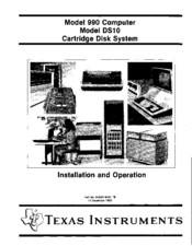
Texas Instruments 990 Installation And Operation Manual (124 pages)
Cartridge Disk System
Brand:
Texas Instruments
| Category:
Computer Hardware
| Size: 8.51 MB
Table of Contents
Table of Contents
5
General
11
Section 1. General Description
11
System Configuration
11
TILINE Bus
12
TILINE Master-To-Slave Write Cycle Timing
13
TILINE Master-To-Slave Read Cycle Timing
14
Disk Controller
15
Interconnection of Disk Controller and Two Disk Drives
16
System Operation
16
Model DSI0 Cartridge Disk Controller (PWB)
17
Model DSI0 Cartridge Disk Controller (Fine Line PWB)
18
Disk Drive Specifications
20
System Specifications
20
Rack Mount Disk Drive Physical Dimensions
21
Cabinet Mount Disk Drive Physical Dimensions
22
Section 2. Installation
25
General
25
Model DSI0 Cartridge Disk System Components
26
Site Requirements
26
Mounting Space Requirements for Rack Mount Disk Drive
26
Mounting Space Requirements for Cabinet Mount Disk Drive
26
Model DSI0 Cartridge Disk System
27
Model 990 Computer
29
Physical Dimensions of Cabinet Mount Model DSIO Cartridge Disk Drive
29
Supportive Environment
30
Cabling Restrictions
30
Unpacking Instructions
30
Unpacking Rack Mount Disk Drive
30
Rack Mount Disk Drive Shipping Configuration
31
Cabinet Mount Disk Drive Shipping Configuration
32
Placement of Disk Drive for Shipping Bolt Removal
33
Carriage Lock Pin Location
35
Unpacking Disk Controller
36
Servo PWB Switch Settings
40
Unpacking Cabinet Mount Disk Drive
41
Data Recovery PWB Switch Settings
41
Disk Controller Shipping Configuration
43
Unpacking Accessories
45
Unpacking, Handling, and Storing Disk Cartridges
45
Unpacking Disk Cartridges
46
Handling Disk Cartridges
46
Storing Disk Cartridges
47
Voltage Conversion Procedures
48
Installation
48
Installation of Rack Mount Disk Drive
48
Disk Drive Input Voltage Jumper Connections
50
Rack Slide Assembly Mounting
51
Installation of Cabinet Mount Disk Drive
52
Computer Chassis Preparation for Disk Controller
53
Reconfiguring Access Granted Circuit for New Chassis Slot
53
Interrupt Connections for 17-Slot Chassis
63
Preparation of Disk Controller
66
Selecting Disk TILINE Address
66
Installation of Disk Controller
66
Installing Disk System Interconnection Cables
66
TILINE Slave Address Switch Settings and Addresses
68
TILINE Slave Address Switches
68
Interconnection Cable Connector Mating
69
Interconnection Cable Dressing in Computer Chassis
70
Cable Adapter
71
Connection of Disk Drive to Ac Power Source
73
XRM (N) Resistor Packs to be Removed from Primary Cabinet
74
Disk Cartridge Installation and Removal
75
Purging the Disk Drive Air Filtering System
75
Disk Cartridge Installation
76
XRM (N) Resistor Packs to be Removed from Primary Rack
74
Switches and Settings for Rack Mount Primary Disk Drive
77
Switches and Settings for Cabinet Mount Primary Disk Drive
78
Disk Cartridge Removal
80
Removal of Disk Cartridge Following Power Failure or for Emergency
82
System Operational Checkout
83
Section 3. Programming
85
Command Completion
85
Command Completion Without Interrupts
87
Command Completion with Interrupts
87
Command Completion Interrupts
87
Seek and Restore Completion Interrupts
87
Command Control
85
General
85
Programming the Disk Controller
85
Control Word 0
87
Control Word 7
87
Format and Sector, Control Word 2
89
Control Words Content and Formats
87
Disk Command Bits
89
Word Count, Control Word 4
90
Control Word 3
90
Control Word 1
92
Disk Commands
94
Store Registers Command
94
Command Format
94
Write Format Command
94
Write Format Command
95
Example of Read Data
96
Read Data Command
98
Read Unformatted Command
98
Header Data Format
96
Read Unformatted Command Example
98
Unformatted Write Command
99
Seek Command
99
Restore Command
99
Example of a Seek Command
99
Formats and Definitions
100
Definition of Terms
100
Sector Format
100
Gap 1
101
Synchronization (Sync) Character
101
Identification (ID) Words
101
Format of a Sector Record Bit Stream
101
Error Detection Code (EDC) Number 1
102
Gap2
102
Data
102
Error Detection Code (EDC) Number 2
102
Gap 3
102
Section 4. Operation
103
Controls and Indicators
103
Ac Circuit ·Breaker
103
DC Circuit Breaker
103
START/STOP Switch/Indicator
103
READY Indicator
104
ACTIVE Indicator
104
F AUL T /RESET Indicator/Switch
104
General
103
Disk Drive Controls and Indicators
104
WRITE/PROTECT CART Indicator/Switch
105
WRITE/PROTECT FIXED Indicator/Switch
105
Disk Cartridge
105
Power Application for Online Operation
106
Disk Cartridge Installation and Removal
106
Disk Cartridge Installation
106
Disk Cartridge Removal
107
Removal of Disk Cartridge Following Power Failure or for Emergency
108
Write Protect
108
Stop and Power Removal
108
Changing Disk Assignments
109
Fault Operating Procedures
109
Operator Preventive Maintenance
109
Operating Instructions
105
Operating Precautions
105
Maintenance Aids
109
Disk Designation Jumper
110
Disk Controller Leos (Pwb Version)
111
Preventive Maintenance
113
Preventive Maintenance for the Rack Mount Disk Drive
113
Preventive Maintenance for the Cabinet Mount Disk Drive
113
Preventive Maintenance for the Cartridge Disk
114
General
114
Maintenance Procedures
115
Disk Contaminants
115
Brush Indicator
118
Texas Instruments 990 Installation And Operation Manual (122 pages)
Video Display Terminal
Brand:
Texas Instruments
| Category:
Desktop
| Size: 3.52 MB
Table of Contents
Table of Contents
5
General
9
Section I. General Description
9
System Terminology
10
Communications Register Unit (CRU)
10
Model 911 VDT Standard Configuration
11
Major Terminal System Components
12
Model 911 VDT Controller Block Diagram
12
VDT Controller
12
Display Unit
13
CRT Monitor
13
Power Supply
13
United States Standard Keyboard Arrangement
14
Control Logic
14
Keyboard
14
Interconnection Cable
14
Purpose of Equipment
15
United States Model 911 VDT Displayed Character Set, Including Graphics Symbols
17
Model 911 VDT International Displayed Characters
18
Terminal Physical Dimensions
19
General
19
Site Requirements
19
Installation
19
Unpacking/Packing
21
Model 911 Video Display and Keyboard Shipping Container
22
Keyboard Shipping Container
23
Remote Installation Cable Routing
24
Terminal Installation
24
Model 911 VDT Kit Cabling Configurations
26
Connection to Computer
27
Location of Controller Circuit Board
27
Installing the Controller
27
Typical Model 911 VDT Controller Board
29
Computerpoweron
30
Terminal Checkout
30
General
33
Terminal Controller Interface
33
Screen Initialization
33
Section III. Programming
33
Displayed Character Positions
37
Keyboard Codes
38
Cursor
44
Sample Routines
44
Keyboard Showing Lowercase Mode Character Positions and Hexadecimal Codes
46
Keyboard Showing Uppercase Mode Character Positions and Hexadecimal Codes
46
Keyboard Showing Control Character Positions and Hexadecimal Codes
46
Keyboard Showing Shift Mode Character Positions and Hexadecimal Codes
47
Echo Character to Screen
48
Read Character from Screen
49
Read Cursor Position
49
Restore Cursor Position
49
Move Cursor
49
Roll up Screen
51
Section IV. Operation
53
General
53
Keyboard
53
United States Model 911 Keyboard
54
Display Unit Control Panel
55
Data Indicator Locations
55
Display Unit Controls and Indicators
56
Data Indicators Sample Pattern
56
Operator Preventive Maintenance
57
Appendix
59
A United Kingdom Model 911 Vdr Keyboard Arrangement, Hexadecimal Codes, Mode Character Positions, ASCII, and Special Character Set
59
B French Model 911 Vdr Keyboard Arrangement, Hexadecimal Codes, Mode Character Positions, ASCII, and Special Character Set
65
C German Model 911 Vdr Keyboard Arrangement, Hexadecimal Codes, Mode Character Positions, ASCII, and Special Character Set
71
D Swedish/Finnish Model911 Vdr Keyboard Arrangement, Hexadecimal Codes, Mode Character Positions, ASCII, and Special Character Set
77
Norwegian/Danish Keyboard Arrangement, Hexadecimal Codes, Mode Character Positions, ASCII, and Special Character Set
83
Japanese Katakana Keyboard Arrangement, Hexadecimal Codes, Mode Character Positions, Modified ASCII (JIS-S), Special Character Set, and Additional Eight-Bit Displayed Character Set
91
Arabic Model 911 VDT Keyboard Arrangement, Device Service Routine Interfaces, and Keyboard Codes
97
French Word Processing Model 911 VDT Keyboard Arrangement, Hexadecimal Codes, Mode Character Positions, ASCII, and Special Character Set
107
Texas Instruments 990 User Manual (122 pages)
Brand:
Texas Instruments
| Category:
Desktop
| Size: 6.46 MB
Table of Contents
Table of Contents
3
IBM 3780 and 2780 Data Communication Terminals
7
Introduction
7
Section I. General Description
7
The Emulator Configuration
7
Features and Capabilities
9
Emulated IBM Features and Capabilities
9
Section II. Functional Description
13
Hardware and Software Requirements
9
Installation
9
Emulated Features and Capabilities
13
Communication Lines
13
Code Structure
13
Introduction
13
Switched Network Control
14
Input/ Output Devices
15
EBCDIC Transparency
17
End of Media (2780 Emulator Users Only)
17
Home Mode
17
Horizontal and Vertical Format Control
17
Binary Data Transmissions/ Receptions
18
Component Selection
18
IS Audible Alarm
20
Multiple Record Transmission
27
Receive Pathname Feature
28
Automatic Call Unit (ACU) Feature
28
Section III. Functional Environment
29
Send Request Feature
28
Introduction
29
Operational Modes
30
Command Prompts
32
Operator Mode
46
Command File Mode
46
Intertask Message Queue Mode
48
Command File Commands
48
I Command File Command (CF)
48
Conditional Command (IF)
67
Wait Command (WAI:)
69
Disconnect Commands
70
Abort Command (ABORT)
70
Disconnect Command (DISC)
70
Terminate Task Command (TERM)
71
Miscellaneous Commands
71
Reset Command (RESET)
71
Statistics Command (ST)
71
Appendixes
79
Emulator Software Requirements
79
Emulator Installation
81
Communication Session
85
Emulator Messages
91
Binary Synchronous Communications Procedures
97
Data Link Control Characters
97
GASCII-EBCDIC Translation Table
103
Command Summary
109
A Emulator Hardware Requirements
115
Texas Instruments 990 Maintenance Manual (58 pages)
Computer TV /EIA Interface Module Depot
Brand:
Texas Instruments
| Category:
Desktop
| Size: 3 MB
Table of Contents
Table of Contents
5
Equipment Overview
8
TTY/EIA Terminal Interface Module
8
Transmit Mode
10
Receive Mode
10
Interrupt Response
10
Character Format
10
Diagnostic Mode
11
Physical Characteristics
11
Electrical Characteristics
11
Module Address
11
Section II. Installation
13
General
13
Unpacking
13
Inspection and Perparation for Installation
13
Installation
13
General
16
Programming
16
Interrupts
18
Status Transitions Affecting New Status Flag
18
Timing Considerations
19
Output Operation
19
Output Character Transfer
20
Output Character String Sample Routine
25
TTY /EIA Terminal Interface Module Detailed Functional Block Diagram
27
DATACLK Baud Rate Selection
29
Active Address Decoder Output for CRUBIT,12-15
29
Receive Go Flag
32
TTY /EIA Receive Switch
33
EIA Line Receivers
33
Receive Buffer Register
33
Detailed Interface Discussion
34
Full Duplex TTY /EIA Module-To-Model 990 Computer Interface
34
Full Duplex TTY/EIA Module-To-Current Loop Device Interface
38
Full Duplex TTY/EIA Module-To-EIA Device Interface
38
Module Operation
39
Preparation to Transmit
39
Data Transmission
39
Data Reception
39
Troubleshooting Procedures
41
Scoping Loops
42
Transmit Go Flag Timing
49
Transmit Shift Clock Generation
49
Transmit Bit Counter Signals
50
Transmit Shift Register Signals
50
Receive Bit Counter Signals
51
Input Operation
53
Error Detection
53
Block Diagram Description
53
Address Decoder
53
Interrupts
53
General
53
Input Character Transfer
53
Echo Character Sample Routine
53
Receive Transition Detector
54
Receive Shift Register
54
Multiplexer
54
Model 990/4 Computer Hot Mock-Up System
54
Model 990/10 Computer Hot Mock-Up System
54
Timing Error Flag
55
Testing
55
Special Test Equipment
55
Transmit Shift Register Logic
55
Troubleshooting Procedures
55
Texas Instruments 990 Maintenance Manual (40 pages)
Computer 16 lnput/16 Output TTL Data Module
Brand:
Texas Instruments
| Category:
Control Unit
| Size: 1.88 MB
Table of Contents
Table of Contents
5
Section I. General Description
7
General
7
Equipment Overview
9
Transmit Mode
9
Receive Mode
9
Interrupt Response
9
Physical Characteristics
11
Electrical Characteristics
11
Module Address
11
General
13
Unpacking
13
Inspection
13
Installation
13
Jumper Connections
13
General
15
Programming
15
Section IV. Theory of Operation
17
General
17
Data Module Input Logic
17
Multiplexer
17
Data Module Output Logic
17
Output Decoder
17
Multiplexer Input Select for CRUBIT
19
Data Selector/Multiplexer
20
Data Module Output Flip-Flop and Timing
21
4-Line-To-16-Line Decoder/Multiplexer
23
Output Flip-Flops
24
Output Transistors
24
Data Module Interrupt Logic
24
Section V. Maintenance
27
General
27
Maintenance Philosophy
27
Special Test Equipment
27
Input/16 Output TTL Data Module
27
Troubleshooting Procedures
30
Scoping Loops
30
Test Procedures
31
Output Line Reference Chart
32
Model 990/4 Computer Hot Mockup System
37
Model 990/10 Computer Hot Mockup System
37
Texas Instruments 990 Installation Manual (16 pages)
16-bit minicomputers
Brand:
Texas Instruments
| Category:
Desktop
| Size: 0.59 MB
Advertisement
Related Products
Texas Instruments 911
Texas Instruments 990/10A
Texas Instruments 99/4A
Texas Instruments 900 Series
Texas Instruments 960B
Texas Instruments 980B
Texas Instruments DLP LightCrafter 9000
Texas Instruments 990A13
Texas Instruments bq28400EVM-001
Texas Instruments Business System 300A
Texas Instruments Categories
Motherboard
Control Unit
Microcontrollers
Computer Hardware
Calculator
More Texas Instruments Manuals
Login
Sign In
OR
Sign in with Facebook
Sign in with Google
Upload manual
Upload from disk
Upload from URL