Sign In
Upload
Manuals
Brands
ST Manuals
Motherboard
STM32L4R9I
ST STM32L4R9I Manuals
Manuals and User Guides for ST STM32L4R9I. We have
1
ST STM32L4R9I manual available for free PDF download: User Manual
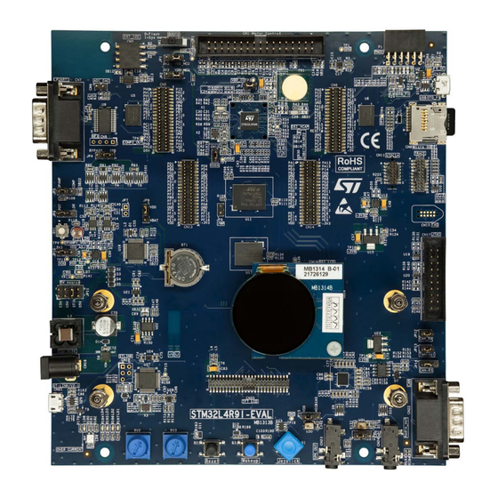
ST STM32L4R9I User Manual (77 pages)
Brand:
ST
| Category:
Motherboard
| Size: 2 MB
Table of Contents
Table of Contents
2
Features
8
Ordering Information
9
Codification
9
Table 1. Ordering Information
9
Table 2. Codification Explanation
9
Development Environment
10
System Requirements
10
Development Toolchains
10
Demonstration Software
10
Conventions
11
Delivery Recommendations
11
Table 3. ON/OFF Conventions
11
Hardware Layout and Configuration
12
Figure 1. STM32L4R9I-EVAL Hardware Block Diagram
12
Figure 2. STM32L4R9I-EVAL Main Board (Top Side)
13
STM32L4R9I-EVAL Main Board Views
14
Figure 3. STM32L4R9I-EVAL Board (Top View) with MB1314 Round DSI Display Daughterboard
14
Figure 4. STM32L4R9I-EVAL Board (Top View) with MB1315 TFT LCD Daughterboard
15
Figure 5. STM32L4R9I-EVAL Board (Bottom View)
16
Mechanical Dimensions
17
Figure 6. MB1313 STM32L4R9I-EVAL Main Board
17
St-Link/V2-1
18
Figure 7. MB1314 DSI Display Daughterboard
18
Drivers
19
ST-LINK/V2-1 Firmware Upgrade
19
ETM Trace
19
Figure 8. USB Composite Device
19
Power Supply
20
Table 4. Setting of Configuration Elements for Trace Connector (CN12)
20
Supplying the Main Board through the ST-LINK/V2-1 USB Port
21
Using ST-LINK/2-1 Along with Powering Via the Power Jack
21
Table 5. Power-Supply-Related Jumpers Settings
22
Clock References
23
Table 6. X1 Crystal-Related Solder Bridge Settings
23
Reset Sources
24
Boot Option
24
Table 7. X2 Crystal-Related Solder Bridge Settings
24
Bootloader Limitations
25
Table 8. Boot Selection Switch
25
Audio
26
Digital Microphones
26
Table 9. Digital Microphone-Related Jumper Settings
26
Headphones Outputs
27
Limitations in Using Audio Features
27
USB OTG FS Port
27
STM32L4R9I-EVAL Used as a USB Device
27
STM32L4R9I-EVAL Used as a USB Host
28
Limitations in Using the USB OTG FS Port
28
Operating Voltage
28
RS232 Port
28
Microsd™ Card
28
Limitations
28
Operating Voltage
29
Motor Control
29
Table 10. Motor-Control Terminal and Function Assignment
29
Board Modifications to Enable Motor Control
31
Limitations
31
Figure 9. PCB Top-Side Rework for Motor Control
32
Figure 10. PCB Bottom-Side Rework for Motor Control
33
Can
34
Limitations
34
Operating Voltage
34
Table 11. CAN Related Jumpers
34
Extension Connectors (CN5, CN6, CN13, and CN14)
35
User Leds
35
Physical Input Devices
36
Limitations
36
Table 12. Port Assignment for Control of Physical Input Devices
36
Operational Amplifier and Comparator
37
Operational Amplifier
37
Comparator
37
Table 13. Configuration Elements Related to Opamp1
37
Limitations
38
Analog Input, Output, VREF
38
Table 14. Configuration Elements Related to Comp2
38
SRAM Device
39
Limitations
39
Operating Voltage
39
NOR Flash Memory Device
39
Table 15. SRAM Chip Select Configuration
39
Limitations
40
Operating Voltage
40
Eeprom
40
EXT_I2C Connector
40
Octo-SPI Flash Memory Device
40
Table 16. nor Flash Memory-Related Jumper
40
Limitations
41
Operating Voltage
41
Octo-SPI DRAM Device
41
Table 17. Configuration Elements Related to Octo-SPI Flash Device
41
Touch-Sensing Button
42
Table 18. Touch-Sensing-Related Configuration Elements
42
Limitations
43
Mfx Mcu
43
Table 19. MFX Signals
43
IDD Measurement
44
Table 20. IDD Measurement-Related Jumper Setting
44
MIPI DSI ® Display Connector
45
Table 21. DSI Display Module Connector (CN16)
45
Limitations
46
TFT LCD (RGB and FMC Mode) Connector
46
Table 22. TFT LCD Module Connector (CN20)
46
Limitations
47
Pmod™ Connector
47
MB1314 DSI Display Daughterboard
47
Table 23. Pmod™ Connector (P1)
47
Table 24. Pin Function Description of the MB1314 Daughterboard Connector (CN1)
47
MB1315 TFT LCD Daughterboard
49
Table 25. Pin Function Description of the MB1315 Daughterboard Connector (CN1)
49
Connectors
50
Motor-Control Connector (CN1)
50
Table 26. Motor-Control Connector (CN1)
50
Figure 11. Motor-Control Connector (CN1) Top View
50
External I 2 C Connector (CN2)
51
USB OTG FS Micro-AB Connector (CN3)
51
Table 27. EXT_I2C Connector (CN2)
51
Table 28. USB OTG FS Micro-AB Connector (CN3)
51
Figure 12. EXT_I2C Connector (CN2) Front View
51
Figure 13. USB OTG FS Micro-AB Connector (CN3) Front View
51
Analog Input-Output Connector (CN4)
52
Extension Connectors (CN5, CN6, CN13, and CN14)
52
Table 29. Analog Input-Output Connector (CN4)
52
Table 30. Daughterboard Extension Connector (CN5)
52
Figure 14. Analog Input-Output Connector (CN4) Top View
52
Table 31. Daughterboard Extension Connector (CN6)
53
Table 32. Daughterboard Extension Connector (CN13)
55
Table 33. Daughterboard Extension Connector (CN14)
56
RS232 Connector (CN7)
58
Microsd™ Connector (CN8)
58
Table 34. RS232 D-Sub Male Connector (CN7)
58
Figure 15. RS232 D-Sub Male Connector (CN7) Front View
58
Figure 16. Microsd™ Connector (CN8) Top View
58
MFX Programming Connector (CN9)
59
STDC14 Connector (CN11)
59
Table 35. Microsd™ Connector (CN8)
59
Table 36. STDC14 Debugging Connector (CN11)
59
Figure 17. STDC14 Debugging Connector (CN11) Top View
59
Trace Debugging Connector (CN12)
60
TAG Connector (CN15)
60
Table 37. Trace Debugging Connector (CN12)
60
Table 38. TAG Debugging Connector (CN15)
60
Figure 18. ETM Trace Debugging Connector (CN12) Top View
60
MIPI DSI ® Display Connector (CN16)
61
JTAG Connector (CN17)
61
Table 39. JTAG/SWD Debugging Connector (CN17)
61
Figure 19. JTAG/SWD Debugging Connector (CN17) Top View
61
Power Connector (CN18)
62
ST-LINK/V2-1 Programming Connector (CN19)
62
RGB TFT LCD Connector (CN20)
62
ST-LINK/V2-1 USB Micro-B Connector (CN21)
62
Figure 20. Power Supply Connector (CN18) Front View
62
Figure 21. USB Micro-B Connector (CN21) Front View
62
CAN D-Type Male Connector (CN22)
63
Figure 22. CAN D-Type 9-Pin Male Connector (CN22) Front View
63
Table 40. USB Micro-B Connector (CN21) Front View
63
Table 41. CAN D-Type 9-Pin Male Connector (CN22)
63
O Assignment
64
Table 42. STM32L4R9I-EVAL I/O Assignment
64
STM32L4R9I-EVAL Product Information
70
Product Marking
70
STM32L4R9I-EVAL Product History
71
Table 43. Product History
71
Board Revision History
73
Table 44. Board Revision History
73
Federal Communications Commission (FCC) and ISED Canada Compliance Statements
74
FCC Compliance Statement
74
ISED Compliance Statement
75
Revision History
76
Table 45. Document Revision History
76
Advertisement
Advertisement
Related Products
ST STM32L4R9I-EVAL
ST STM32L4 Series
ST STM32L476G-EVAL
ST STM32L476ZG
ST STM32L073Z-EVAL
ST STM32L152-EVAL
ST STM32L152VB
ST STM32L1 Series
ST STM32L-DISCOVERY
ST STM32L152RCT6 Discovery kit
ST Categories
Motherboard
Computer Hardware
Microcontrollers
Control Unit
Controller
More ST Manuals
Login
Sign In
OR
Sign in with Facebook
Sign in with Google
Upload manual
Upload from disk
Upload from URL