Sign In
Upload
Manuals
Brands
ST Manuals
Motherboard
STM32L152VB
ST STM32L152VB Manuals
Manuals and User Guides for ST STM32L152VB. We have
1
ST STM32L152VB manual available for free PDF download: Application Note
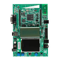
ST STM32L152VB Application Note (30 pages)
Getting started with hardware development
Brand:
ST
| Category:
Motherboard
| Size: 0 MB
Table of Contents
Introduction
1
Table of Contents
2
Power Supplies
6
Introduction
6
Figure 1. Power Supply Overview
6
Independent A/D Converter Supply and Reference Voltage
7
Independent LCD Supply
8
Voltage Regulator
8
Power Supply Schemes
9
Reset and Power Supply Supervisor
9
Figure 2. Power Supply Scheme
9
Figure 3. Power Supply Supervisors
10
Figure 4. Power on Reset/Power down Reset Waveform
11
Power-On Reset (Por)/Power-Down Reset (PDR), Brownout Reset (BOR)
11
Programmable Voltage Detector (PVD)
11
Brownout Reset (BOR)
12
Figure 5. PVD Thresholds
12
Figure 6. Reset Circuit
13
System Reset
13
Clocks
14
MSI Clock
14
HSE OSC Clock
15
External Source (HSE Bypass)
15
External Crystal/Ceramic Resonator (HSE Crystal)
15
Figure 7. External Clock
15
Figure 8. Crystal/Ceramic Resonators
15
LSE OSC Clock
16
External Source (LSE Bypass)
16
External Crystal/Ceramic Resonator (LSE Crystal)
16
Figure 9. External Clock
16
Clock Security System (CSS)
17
Boot Configuration
18
Boot Mode Selection
18
Boot Pin Connection
18
Table
18
Boot Modes
18
Figure 11. Boot Mode Selection Implementation Example
18
Embedded Boot Loader Mode
19
Debug Management
20
Introduction
20
SWJ Debug Port (Serial Wire and JTAG)
20
Pinout and Debug Port Pins
20
Figure 12. Host-To-Board Connection
20
Flexible SWJ-DP Pin Assignment
21
SWJ Debug Port Pins
21
Table
21
Debug Port Pin Assignment
21
SWJ I/O Pin Availability
21
Internal Pull-Up and Pull-Down Resistors on JTAG Pins
22
SWJ Debug Port Connection with Standard JTAG Connector
22
Figure 13. JTAG Connector Implementation
22
Recommendations
23
Printed Circuit Board
23
Component Position
23
Ground and Power Supply (VSS , VDD )
23
Decoupling
23
Other Signals
24
Unused I/Os and Features
24
Figure 14. Typical Layout for V
24
DD /VSS Pair
24
Reference Design
25
Description
25
Clock
25
Reset
25
Boot Mode
25
SWJ Interface
25
Power Supply
25
Component References
26
Figure 15. STM32L152VB(T6) Microcontroller Reference Schematic
27
Table 6. Reference Connection for All Packages
28
Revision History
29
Advertisement
Advertisement
Related Products
ST STM32L152-EVAL
ST STM32L1 Series
ST STM32L152VBT6
ST STM32L152RCT6 Discovery kit
ST STM32L152RBT6
ST STM32L152C-DISCO
ST STM32L4 Series
ST STM32L-DISCOVERY
ST STM32L476ZG
ST STM32L4R9I
ST Categories
Motherboard
Computer Hardware
Microcontrollers
Control Unit
Controller
More ST Manuals
Login
Sign In
OR
Sign in with Facebook
Sign in with Google
Upload manual
Upload from disk
Upload from URL