Sign In
Upload
Manuals
Brands
ST Manuals
Motherboard
STM32L073Z-EVAL
ST STM32L073Z-EVAL Manuals
Manuals and User Guides for ST STM32L073Z-EVAL. We have
2
ST STM32L073Z-EVAL manuals available for free PDF download: User Manual
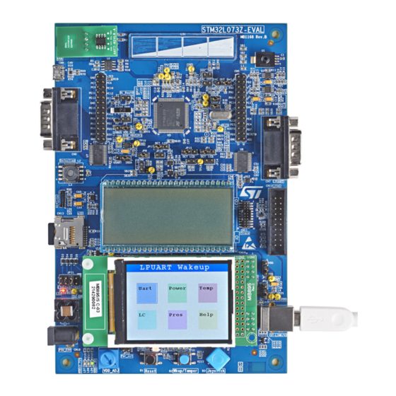
ST STM32L073Z-EVAL User Manual (64 pages)
with STM32L073VZ MCU
Brand:
ST
| Category:
Motherboard
| Size: 4 MB
Table of Contents
Table of Contents
2
Features
7
Product Marking
8
System Requirements
8
Development Toolchains
8
Demonstration Software
9
Ordering Information
9
Table 1. Ordering Information
9
Hardware Layout and Configuration
10
Figure 2. Hardware Block Diagram
10
Embedded ST-LINK/V2-1
11
Figure 3. STM32L073Z-EVAL Evaluation Board (Top View)
11
Drivers
12
Figure 4. USB Composite Device
12
ST-LINK/V2-1 Firmware Upgrade
12
SWD Connectors
13
Power Supply
13
Figure 5. Pin-Out of 5 V DC Adapter
13
Table 2. Power Related Jumpers
14
Adjustable Power Supply
16
Clock Source
17
Reset Sources
17
Table 3. 32.768 Khz Crystal X2 Solder Bridges
17
Table 4. 8 Mhz Crystal X1 Solder Bridges
17
Boot Option
18
Table 5. Boot Related Switch
18
Usb Fs
19
Operating Voltage
19
Smbus Temperature Sensor
19
Table 6. Boot Related Jumper
19
Limitations
20
Operating Voltage
20
RS-232 USART2 and Irda
20
Irda
20
Table 7. Temperature Sensor Related Solder Bridge
20
Table 8. RS-232 and Irda Jumper Settings
20
Limitations
21
Operating Voltage
21
Rs-232 Lpuart
21
Virtual Com Port
21
Limitations
22
Operating Voltage
22
Microsd Card
22
Analog Input ADC
22
Table 9. Microsd Connector CN13
22
Figure 6. Location of ADC Input Connector CN2
23
Figure 7. Provision for Filter Implementation
23
Operating Voltage
24
Analog Output DAC
24
Figure 8. Location of DAC Output CN3 and JP2
24
Figure 9. Provision for Filter Implementation
25
Limitations
25
Operating Voltage
25
Table 10. Analog Input Related Jumper JP2 Settings
25
TFT LCD Display
26
Limitations
26
Operating Voltage
26
User Leds
26
Table 11. TFT LCD Connector
26
Table 12. User Leds
26
Input Devices
27
Rf-Eeprom
27
LCD Glass Display Module
27
Figure 1. STM32L073Z-EVAL Evaluation Board
27
Table 13. Input Devices
27
Figure 10. LCD Glass Board in LCD Position
28
Figure 11. LCD Glass Board in IO Position
28
Table 14. LCD Glass Segments 21 to 28 Mapping Table
28
Table 15. LCD Glass Segments 0 and 29 to 39 Mapping Table
29
Table 16. LCD Glass Segments 1 to 8, 15, 18 to 20 Mapping Table
29
Table 17. LCD Glass Segments 9 to 14, 16, 17 Mapping Table
29
Figure 12. LCD Segment Names
30
Table 18. LCD Glass Related Jumpers and Solder Bridges
30
Limitations
31
LC Sensor Metering
31
LC Sensor Metering Principle
32
Figure 13. Functional Block Diagram of LC Sensor Metering
32
LC Sensor Metering Description
33
Figure 14. LC Sensor Metering Schematic
33
Table 19. Solder Bridges and Jumpers for LC Sensor Metering
34
Limitations
35
Pressure Sensor
35
Calculations
35
Table 20. Sensor Differential Voltage
36
Table 21. Differential Voltage
36
Figure 15. Differential Amplifier with Offset Correction
36
Errors
37
Pressure Computation
37
Filtering
37
Table 22. Single Output Voltage to the ADC
37
Limitations
38
Operating Voltage
38
Touch Sensing Slider
38
Table 23. Touch Sensing Related Solder Bridges
38
Limitations
39
Extension Connectors
39
Figure 16. Solder Bridges Settings to Enable the Touch Slider (Red = Closed, Green = Opened)
39
IDD Auto-Measurement
40
Table 24. Extension Connectors Pin-Out
40
Analog Section Description
41
Figure 17. Figure: Analog Section Schematic
41
Table 25. IDD Auto-Measurement Related Jumper Settings
41
Difference Amplifier
42
Digital Section Description
42
Figure 18. Difference Amplifier
42
Figure 19. Digital Section Schematic
43
Connectors
44
RS-232 Connector CN6
44
Power Connector CN18
44
Table 26. RS-232 Connector CN6
44
Figure 20. RS-232 Connector CN6 (Front View)
44
Figure 21. Power Supply Connector CN18
44
LCD Glass Daughterboard Connectors CN10 and CN14
45
Table 27. LCD Glass Daughterboard Connectors
45
ST-LINK/V2-1 Programming Connector CN15
46
ST-LINK/V2-1 USB Type B Connector CN17
46
Table 28. USB Type B Connector CN17
46
Figure 22. USB Type B Connector CN17
46
SWD Connector CN12
47
Trace Debugging Connector CN11
47
Table 29. SWD Debugging Connector CN12
47
Figure 23. Trace Debugging Connector CN12 (Top View)
47
Figure 24. Trace Debugging Connector CN11 (Top View)
47
Microsd Connector CN3
48
Table 30. Trace Debugging Connector CN11
48
Table 31. Microsd Connector CN3
48
Figure 25. Microsd Connector CN3
48
RF-EEPROM Daughterboard Connector CN3
49
Table 32. RF-EEPROM Daughterboard Connector CN3
49
Figure 26. RF-EEPROM Daughterboard Connector CN3 (Front View)
49
Appendix A Electrical Schematics
50
Figure 27. STM32L073Z-EVAL
50
Figure 33. USART_LPUART
50
Figure 28. MCU
51
Figure 29. LCD Glass External Connector
52
Figure 30. Power
53
Figure 31. Peripherals
54
Figure 32. TFT Microsd
55
Figure 34. Pressure Sensor
57
Figure 35. LC Sensor Metering
58
Figure 36. IDD Measurement
59
Figure 37. SWD, Touch, USB
60
Figure 38. ST-LINK/V2-1
61
Appendix B Mechanical Dimensions
62
Figure 39. Mechanical Dimensions
62
Revision History
63
Table 33. Document Revision History
63
Advertisement
ST STM32L073Z-EVAL User Manual (57 pages)
Brand:
ST
| Category:
Motherboard
| Size: 2 MB
Table of Contents
Table of Contents
2
Features
7
Ordering Information
8
Codification
8
Table 1. List of Available Products
8
Table 2. Codification Explanation
8
Development Environment
9
System Requirements
9
Development Toolchains
9
Demonstration Software
9
Hardware Layout and Configuration
10
Figure 2. Hardware Block Diagram
10
Embedded ST-LINK/V2-1
11
Figure 3. STM32L073Z-EVAL Evaluation Board (Top View)
11
Drivers
12
Figure 4. USB Composite Device
12
ST-LINK/V2-1 Firmware Upgrade
13
SWD Connectors
13
Power Supply
13
Figure 5. Pin-Out of 5 V DC Adapter
13
Table 3. Power Related Jumpers
14
Adjustable Power Supply
16
Clock Source
17
Reset Sources
17
Table 4. 32.768 Khz Crystal X2 Solder Bridges
17
Table 5. 8 Mhz Crystal X1 Solder Bridges
17
Boot Option
18
Table 6. Boot Related Switch
18
Usb Fs
19
Operating Voltage
19
Smbus Temperature Sensor
19
Table 7. Boot Related Jumper
19
Limitations
20
Operating Voltage
20
RS-232 USART2 and Irda
20
Irda
20
Table 8. Temperature Sensor Related Solder Bridge
20
Table 9. RS-232 and Irda Jumper Settings
20
Limitations
21
Operating Voltage
21
Rs-232 Lpuart
21
Virtual COM Port
21
Limitations
22
Operating Voltage
22
Microsd™ Card
22
Analog Input ADC
22
Table 10. Microsd™ Connector CN13
22
Figure 6. Location of ADC Input Connector CN2
23
Figure 7. Provision for Filter Implementation
23
Operating Voltage
24
Analog Output DAC
24
Figure 8. Location of DAC Output CN3 and JP2
24
Limitations
25
Operating Voltage
25
Table 11. Analog Input Related Jumper JP2 Settings
25
Figure 9. Provision for Filter Implementation
25
TFT LCD Display
26
Limitations
26
Operating Voltage
26
User Leds
26
Table 12. TFT LCD Connector
26
Table 13. User Leds
26
Input Devices
27
Rf-Eeprom
27
LCD Segments
27
Table 14. Input Devices
27
Table 15. LCD Segments 21 to 28 Mapping Table
28
Figure 10. LCD Segment Daughterboard in LCD Position
28
Figure 11. LCD Segment Daughterboard in "IO" Position
28
Table 16. LCD Segments 0 and 29 to 39 Mapping Table
29
Table 17. LCD Segments 1 to 8, 15, 18 to 20 Mapping Table
29
Table 18. LCD Segments 9 to 14, 16, 17 Mapping Table
29
Table 19. LCD Segments Related Jumpers and Solder Bridges
30
Figure 12. LCD Segment Names
30
Limitations
31
LC Sensor Metering
31
LC Sensor Metering Principle
32
Figure 13. Functional Block Diagram of LC Sensor Metering
32
LC Sensor Metering Description
33
Figure 14. LC Sensor Metering Schematic
33
Table 20. Solder Bridges and Jumpers for LC Sensor Metering
34
Limitations
35
Pressure Sensor
35
Calculations
35
Table 21. Sensor Differential Voltage
36
Table 22. Differential Voltage
36
Figure 15. Differential Amplifier with Offset Correction
36
Errors
37
Pressure Computation
37
Filtering
37
Table 23. Single Output Voltage to the ADC
37
Limitations
38
Operating Voltage
38
Touch-Sensing Slider
38
Table 24. Touch Sensing Related Solder Bridges
38
Limitations
39
Extension Connectors
39
Figure 16. Solder Bridges Settings to Enable the Touch Slider (Red = Closed, Green = Opened)
39
IDD Auto-Measurement
40
Table 25. Extension Connectors Pin-Out
40
Analog Section Description
41
Table 26. IDD Auto-Measurement Related Jumper Settings
41
Figure 17. Figure: Analog Section Schematic
41
Difference Amplifier
42
Digital Section Description
42
Figure 18. Difference Amplifier
42
Figure 19. Digital Section Schematic
43
Connectors
44
RS-232 Connector CN6
44
Power Connector CN18
44
Table 27. RS-232 Connector CN6
44
Figure 1. STM32L073Z-EVAL Evaluation Board
44
Figure 20. RS-232 Connector CN6 (Front View)
44
Figure 21. Power Supply Connector CN18
44
LCD Segment Daughterboard Connectors CN10 and CN14
45
Table 28. LCD Segment Daughterboard Connectors
45
ST-LINK/V2-1 Programming Connector CN15
46
ST-LINK/V2-1 USB Type-B Connector CN17
46
Table 29. USB Type-B Connector CN17
46
Figure 22. USB Type-B Connector CN17
46
SWD Connector CN12
47
Trace Debugging Connector CN11
47
Table 30. SWD Debugging Connector CN12
47
Figure 23. Trace Debugging Connector CN12 (Top View)
47
Figure 24. Trace Debugging Connector CN11 (Top View)
47
Microsd™ Connector CN13
48
Table 31. Trace Debugging Connector CN11
48
Table 32. Microsd™ Connector CN13
48
Figure 25. Microsd™ Connector CN13
48
RF-EEPROM Daughterboard Connector CN1
49
Table 33. RF-EEPROM Daughterboard Connector CN1
49
Figure 26. RF-EEPROM Daughterboard Connector CN1 (Front View)
49
Mechanical Dimensions
50
Figure 27. Mechanical Dimensions
50
STM32L073Z-EVAL Evaluation Board Information
51
Product Marking
51
STM32L073Z-EVAL Product History
52
Table 34. Product History
52
Board Revision History
53
Table 35. Board Revision History
53
Federal Communications Commission (FCC) and ISED Canada Compliance Statements
54
FCC Compliance Statement
54
Part 15.19
54
Part 15.21
54
Part 15.105
54
ISED Compliance Statement
55
Revision History
56
Table 36. Document Revision History
56
Advertisement
Related Products
ST STM32L4R9I-EVAL
ST STM32L152-EVAL
ST STM32L1 Series
ST STM32L152VBT6
ST STM32L476G-EVAL
ST STM32L152RBT6
ST STM32L152C-DISCO
ST STM32L4R9I
ST STM32L476ZG
ST STM32L021F4
ST Categories
Motherboard
Computer Hardware
Microcontrollers
Control Unit
Controller
More ST Manuals
Login
Sign In
OR
Sign in with Facebook
Sign in with Google
Upload manual
Upload from disk
Upload from URL