Sign In
Upload
Manuals
Brands
Simrad Manuals
Marine Equipment
EY500
Simrad EY500 Manuals
Manuals and User Guides for Simrad EY500. We have
1
Simrad EY500 manual available for free PDF download: Instruction Manual
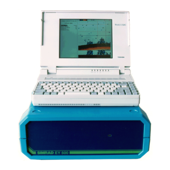
Simrad EY500 Instruction Manual (263 pages)
Portable scientific echo sounder
Brand:
Simrad
| Category:
Marine Equipment
| Size: 14.68 MB
Table of Contents
Table of Contents
9
1 Introduction
11
General
11
Description of the Equipment
12
Configuration
12
EY 500 System Modules
12
Simplified Block Diagram
13
EY 500 Transceiver, Simplified Block Diagram
13
Interconnections
14
EY 500 Rear Interconnection Panel
14
2 Technical Specifications
15
Common Specifications for Single-Beam and Split-Beam Versions
15
Specifications Valid for Split-Beam Version Only
15
Minimum PC Specification
16
Options
16
Power System
16
Transceiver
17
Transceiver Parameters
17
Maximum Detection Range for Different Transducers
18
Transceiver Dimensions and Weight
18
Printer Specifications
19
Echogram Layout on Display and Printer
39
Introduction
39
The Interactive Menu System
39
Display Layout
40
The Colour Scale
40
Display Echogram
41
Layer Lines
41
Super Layer
41
Bottom Range Echogram
42
Integration Line
42
Bottom Detection Line
45
Event Marker
45
Scale Lines
45
Colour Printer Echogram
46
Nautical Mile Marker
46
Annotation
47
Date and Time Stamp
47
TS Distribution Table
47
Integration Table
48
Navigation Data
49
Range and Identification Fields
49
Scope Plot Showing 300 Samples of Transceiver Data
53
40 Log Echogram on Display
54
Operation Examples
54
Start of Pinging
54
20 Log Echogram on the Printer
55
Defining the Calculating Interval
55
Defining the Layer Picture
55
Limiting the Bottom Detection Range
56
Monitoring of Data
56
Sending Data to Disk
56
The Ey 500 File System
57
The Replay Function
58
Menu Descriptions
60
The Main Menu
60
Ping Auto Start
61
Ping Mode
61
The Operation Menu
61
Ping Interval
62
Colour Set
63
The Display Menu
63
Echogram
64
Echogram Speed
64
The Display/Echogram Menu
65
Transd. Number
65
Auto Range
66
Bottom Range
66
Range
66
Range Start
66
Bot. Range Pres.
67
Presentation
67
Sub. Bottom Gain
67
Bot. Det. Line
68
Tvg
68
Model Type
70
Navig. Interval
70
The Printer Menu
70
The Printer/Echogram Menu
73
The Transceiver Menu
74
Mode
75
Transd. Sequence Options
75
Transducer Type
75
Absorption Coef
76
Transducer Depth Options
76
Bandwidth
77
Pulse Length
77
2-Way Beam Angle Options
78
Max. Power
78
Sv Transd. Gain
78
TS Transd. Gain
78
3 Db Beamw. Along
79
3 Db Beamw. Athw.
79
Angle Sens. Along
79
Angle Sens. Athw.
79
Alongship Offset
80
Athw.ship Offset Options
80
Minimum Depth
81
The Bottom Detection Menu
81
Bottom Lost Alarm Options
82
Max. Depth Alarm Options
82
Maximum Depth Options
82
Min. Depth Alarm Options
82
The Log Menu
83
Dist. Interval
84
Distance
84
Time Interval
84
The Layer Menu
85
The Layer Submenus
87
Margin
88
Sv Threshold
88
The Ts Detection Menu
89
The TS Detection Submenu
90
Max. Echo Length Options
91
Max. Gain Comp
91
Min. Echo Length
91
Min. Value
91
Max. Phase Dev
92
Log
93
Max. File Size
93
The Disk Menu
93
Directory
94
Drive
94
Replay File Name
94
Replay Forever
94
The Disk/Telegram Menu
95
The Disk/Echogram Menu
97
No. of Bot. Val
98
No. of Main Val. Options
98
The Serial Communication Menu
100
Format
101
The Serial/Telegram Menu
101
Modem Control
102
Parameter
102
Remote Control
102
Depth
103
Depth NMEA
103
Layer
104
Vessel-Log
104
Baudrate
105
Bits Per Char
105
Stop Bits
105
The SERIAL/USART Menu
105
The Serial/Echogram Menu
106
Counter Mode
109
Event Counter
109
The Annotation Menu
109
Text
110
The Navigation Menu
111
Navig. Input
112
Separation Char
112
Start Sequence
112
Stop Character
112
Bits Per Char.
113
Manual Speed
113
Speed Input
113
Parity
114
Ascii Characters Versus Hexadecimal Representation
115
Beeper
116
Date
116
Status Messages
116
The Utility Menu
116
Default Settings
117
External Clock
117
Password
117
Sound Velocity
117
Com1/Com2
118
The Test Menu
119
Theory of Operation
121
List of Contents
123
Document History
124
General Description
125
Introduction
125
Power Budget
125
The Signal Processing
125
The Transceiver
125
The Gain Concept
126
Beam Pattern
127
Bottom Detection
131
Ey 500 Db Format
131
Bottom Range
132
Echo Integration
132
Split-Beam Operation
134
Split-Beam Transducer
134
Split-Beam Principle
135
Impulse Response
136
Signal Envelopes
136
Noise
137
Receiver Noise Versus Ambient Noise
137
Absorption Coefficient
138
Sound Absorption
138
Sound Velocity Diagram
139
Description of Telegrams and Remote Control
141
General
145
Serial Communication Port
145
Output Telegrams
146
Asynchronous Output Telegrams
147
Ping-Based Output Telegrams
147
Examples of Log-Based Output Telegrams
149
Ll
149
Log-Based Output Telegrams
149
Vl
149
H1
150
Input Telegrams
150
Ey500.Par
151
General
151
Modahomi.dgy
151
The Disk Storage
151
Asynchronous Output
152
Ping Based Output
154
Log Based Output
157
Maintenance
159
Transceiver with PC
164
Inside View of the Transceiver
165
Rear Interconnection Panel
166
Introduction
167
Technical Description
167
Transceiver Block Diagram
167
Demultiplexer
168
Functional Description
168
Pc Interface Board
168
Transducer Coding Port
168
PC Interface Board, Block Diagram
169
Maintenance Aids
171
P7
171
Amplitude Part
172
Digital Transceiver Board
172
Phase Part
172
Digital Transceiver Board
173
Eprom
175
Links
175
Test Points
175
Analog Transceiver Board
176
Receiver
176
Transmitter
176
Leds
180
Connections
182
DC Power Supply
182
Backplane
184
Preventive Maintenance
186
Built- in Test Functions
187
Corrective Maintenance
187
Fuses and Test Points
187
Visual Check
187
Built-In Test Functions
188
Internal Test
188
Self- Test Procedure for Printer
188
Transceiver Test
188
Fault- Findingp Rocedure
189
Introduction
192
Removing the Upper Cover
192
Replacing the PCB Modules
192
Replacing the DC Power Supply
194
Introduction
196
List of Messages
196
Error Messages Concerning Signal Processing
198
Display Data Error
200
Printer Data Error
200
Transd. Parameter Error
200
Printed Circuit Boards
202
Spare Parts List
202
Transceiver
202
Calibration of the Ek 500 / Ey 500
203
The Purpose of Calibration
207
Calibration Procedure
208
Check the Hardware Installation
208
Check the Internal Test Oscillator
208
Rigging
208
Attaching the Sphere
210
Lowering the Sphere
210
Reference Target.
211
Simrad Copper Spheres
211
Sound Speed in Water
212
Centering of Split Beam
213
Select the Display/Echogram Menu and Set
213
Select the Log Menu and Set
213
Select the Operation Menu and Set
213
Select the Layer Menu/Layer-1 Menu and Set
214
Select the TS-Detection Menu and Set
214
Centering of Single Beam
215
TS-Measurement
217
The Lobe Calibration Program
219
Unpacking and Startup
219
Operating Procedure
220
Noise Measurements at Sea
226
Drawings
235
Advertisement
Advertisement
Related Products
SIMRAD ER60 - REV B
SIMRAD ES70 - REV A
SIMRAD ES60 - DATASHEET REV A
Simrad EQ44
Simrad EQ54
Simrad ED162
Simrad ER60
Simrad EQ33
Simrad ES80
Simrad EK80
Simrad Categories
Marine Equipment
Transducer
Sonar
Autopilot System
Accessories
More Simrad Manuals
Login
Sign In
OR
Sign in with Facebook
Sign in with Google
Upload manual
Upload from disk
Upload from URL