Siemens SENTRON PAC3100 Manuals
Manuals and User Guides for Siemens SENTRON PAC3100. We have 3 Siemens SENTRON PAC3100 manuals available for free PDF download: Manual, Operating Instructions Manual

Siemens SENTRON PAC3100 Manual (184 pages)
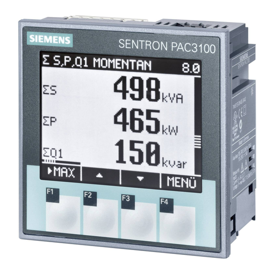
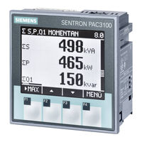
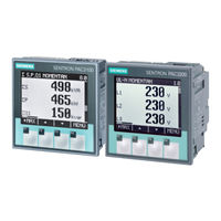
Power Monitoring Device
Brand: Siemens
|
Category: Measuring Instruments
|
Size: 7 MB
Table of Contents
Advertisement
Siemens SENTRON PAC3100 Manual (152 pages)
Power Monitoring Device
Brand: Siemens
|
Category: Measuring Instruments
|
Size: 5 MB
Table of Contents
Siemens SENTRON PAC3100 Operating Instructions Manual (8 pages)
Brand: Siemens
|
Category: Measuring Instruments
|
Size: 1 MB
Advertisement
Advertisement