Sign In
Upload
Manuals
Brands
Siemens Manuals
Transmitter
7NG3092-8KN
Siemens 7NG3092-8KN Manuals
Manuals and User Guides for Siemens 7NG3092-8KN. We have
1
Siemens 7NG3092-8KN manual available for free PDF download: Operating Instructions Manual
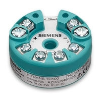
Siemens 7NG3092-8KN Operating Instructions Manual (236 pages)
Temperature transmitter with 4to 20 mA/HART
Brand:
Siemens
| Category:
Transmitter
| Size: 11 MB
Table of Contents
Table of Contents
3
1 Getting Started
11
SITRANS TH100 Commissioning
11
Commissioning SITRANS TH320 with 4 to 20 Ma
12
Commissioning SITRANS TH320 with HART
13
Commissioning SITRANS TH420 with HART
14
Commissioning SITRANS TR320 with 4 to 20 Ma
15
Commissioning SITRANS TR320 with HART
16
Commissioning SITRANS TR420 with HART
17
Commissioning SITRANS TF320 Single Chamber Housing with 4 to 20 Ma
18
Commissioning SITRANS TF320 Single Chamber Housing with HART
18
Commissioning SITRANS TF420 Single Chamber Housing with HART
19
1.11 Commissioning SITRANS TF320 Dual Chamber Housing with 4 to 20 Ma
20
Commissioning SITRANS TF320 Dual Chamber Housing with HART
21
Commissioning SITRANS TF420 Dual Chamber Housing with HART
22
2 Introduction
23
Purpose of this Documentation
23
Functional Safety Manual
23
Document History
23
Product Compatibility
24
USB Modem: Information on Industrial Use
24
Checking the Consignment
24
Security Information
25
Transportation and Storage
25
Notes on Warranty
26
3 Safety Notes
27
Prerequisites for Safe Use
27
Warning Symbols on the Device
27
Laws and Directives
27
Conformity with European Directives
27
Improper Device Modifications
28
Requirements for Special Applications
28
Use in Hazardous Areas
28
4 Description
31
Sitrans Th100
31
Application Range
31
Structure
32
How TH100 Works
33
Sitrans Th320/Th420
34
Application
34
Structure
35
Meaning of the Jumper Positions
36
Nameplate Layout SITRANS TH
36
LED Function
37
Test Terminals
38
How TH320 Works
39
How TH420 Works
40
HART Communication
41
HART Communication with Supply from Voltage Source
41
HART Communication with Supply Via Isolating Power Supply
42
Sitrans Tr320/Tr420
43
Application
43
Structure
44
Meaning of the Jumper Positions
45
Nameplate Layout SITRANS TR
46
LED Function
46
Test Terminals
47
How TR320 Works
48
How TR420 Works
49
HART Communication
50
HART Communication with Supply from Voltage Source
50
HART Communication with Supply Via Isolating Power Supply
51
Sitrans Tf320/Tf420
52
Application
52
Single Chamber Housing Design
52
Nameplate Layout SITRANS TF Single Chamber Housing
53
Dual Chamber Housing Design
54
Nameplate Layout SITRANS TF Dual Chamber Housing
55
How TF320 Works
56
How TF420 Works
57
USB Modem and SIPROM T
58
Applications
58
Product Features
58
Meaning of Leds on the USB Modem
59
5 Installing/Mounting
61
Basic Safety Notes
61
Atex/Iecex and Others
61
Safety Information for Installation in "Intrinsic Safety "Ia/Ib
61
Safety Information for Installation in "Non-Sparking Na/Ec" and "Intrinsic Safety IC
62
Fm/Csa
63
Safety Information for Installation in "Intrinsic Safety "Ia
63
Safety Information for Installation in "Non Incendive Na
64
Sitrans Tf
65
Installing SITRANS TH in a Connection Head
65
Installing the Transmitter in the Base of the Connection Head
65
Installing the Transmitter in the Raised Cover of the Connection Head
66
Installing SITRANS TH on DIN Rail and G Rail
67
Installing SITRANS TR on DIN Rail
68
Mounting the SITRANS TF Single Chamber Housing
69
Mounting the Device on the Wall or Pipe
69
Rotating the Display
69
Mounting the SITRANS TF Dual Chamber Housing
70
Mounting Device to a Pole with Mounting Bracket
70
Mounting Device to the Wall with Mounting Bracket
71
Rotating the Display
72
Mount Adapter M20X1.5-PG13.5
74
Mount Adapter for Connector Socket Han7D/Han8D
74
Removing
76
6 Connecting
77
Basic Safety Notes
77
Connecting the TH100
79
Connecting TH320
80
Connecting TH420
81
Connecting TR320
83
Connecting TR420
85
Connecting the SITRANS TF Single Chamber Housing
88
Opening the Device
88
Connecting the SITRANS TF320 Single Chamber Housing
88
Connecting the SITRANS TF420 Single Chamber Housing
91
Closing the Device
94
Connecting the SITRANS TF Dual Chamber Housing
95
Opening the Device
95
Connecting the SITRANS TF320 Dual Chamber Housing
95
Connecting the SITRANS TF420 Dual Chamber Housing
97
Closing the Device
100
Connect the Han Cable Socket to the Cable
100
Connect M12 Cable Socket to the Cable
101
7 Operating (SITRANS TF)
105
Local Operation
105
Buttons
105
Single Chamber Housing Buttons
105
Dual Chamber Housing Buttons
106
Operating the Device with Display
107
Navigating in the Views
107
Measurement View
108
Parameter View
109
Edit View
110
Device Status Display
112
Remote Operation
112
Locking the Device
112
Introduction
112
Enable Write Protection with Write Protection Switch
113
Enable the User PIN on the Display
114
Enable the Button Lock on the Display
114
8 Commissioning
117
Basic Safety Notes
117
SITRANS TH100 Commissioning
117
Commissioning SITRANS TH320 with 4 to 20 Ma
118
Commissioning SITRANS TH320 with HART
119
Commissioning SITRANS TH420 with HART
120
Commissioning SITRANS TR320 with 4 to 20 Ma
121
Commissioning SITRANS TR320 with HART
122
Commissioning SITRANS TR420 with HART
123
Commissioning SITRANS TF320 Single Chamber Housing with 4 to 20 Ma
123
Commissioning SITRANS TF320 Single Chamber Housing with HART
124
Commissioning SITRANS TF420 Single Chamber Housing with HART
125
8.12 Commissioning SITRANS TF320 Dual Chamber Housing with 4 to 20 Ma
126
Commissioning SITRANS TF320 Dual Chamber Housing with HART
127
Commissioning SITRANS TF420 Dual Chamber Housing with HART
127
Switching on the Supply Voltage
128
Commissioning the USB Modem and SIPROM T
129
Fundamental Safety Instructions
129
Installing the SIPROM T Parameterization Software
129
Connecting USB Modem
131
9 Parameter Assignment
133
Overview of Parameters and Functions
133
Parameters and Functions
133
Advanced Functions
136
Parameter Assignment with USB Modem and SIPROM T
137
Parameter Assignment over Device with Display
138
Input Type 1 [01]
138
Connection Type for Input 1 [02]
142
Wire Resistance for Connecting Cable at Input 1 [03]
142
Input Type 2 [04]
142
Connection Type for Input 2 [05]
145
Wire Resistance for Connecting Cable at Input 2 [06]
146
Assignment of the Primary Variable [07]
146
Introduction
146
Setting the Assignment of the Primary Variable
147
Unit [08]
147
Lower Range Value [09]/Upper Range Value [10]
148
Lower Range Value [09] Parameter
148
Upper Range Value [10] Parameter
148
Adjusting Lower Range Value/Upper Range Value
148
Damping Value [11]
149
Damping Value Parameter
149
Set Damping Value
149
Functional Safety [12]
150
Loop Test [13]
150
Loop Test with Preset Loop Current Value
150
Loop Test with User Defined Loop Current Value
151
One-Point Calibration Input 1 [14]
152
One-Point Calibration Input 2 [15]
152
Change User PIN [16]
152
Change User PIN
152
PIN Recovery [17]
153
Recovering the User PIN
154
User PIN [18]
155
User PIN
155
Enable User PIN
155
Disable User PIN
155
Minimum Measured Peak Value at Input 1 [19]
156
Maximum Measured Peak Value at Input 1 [20]
156
Minimum Measured Peak Value at Input 2 [21]
157
Maximum Measured Peak Value at Input 2 [22]
157
Minimum Transmitter Electronics Temperature [23]
157
Maximum Transmitter Electronics Temperature [24]
157
Button Lock [25]
157
Enabling Button Lock
158
Disabling Button Lock
158
Assigning Parameters Using Remote Operation
159
Introduction
159
Quick Start" Wizard
159
Identification
160
User-Specific Type
160
Introduction
160
Set the Linearization Table (60 Breakpoints)
162
Set the Spline Curve (40 Breakpoints)
162
Sensor Calibration
162
Introduction
162
Setting One-Point Calibration
163
Setting Two-Point Calibration
164
Transmitter Sensor Matching
165
Introduction
165
Changing the Callendar-Van Dusen Coefficients
166
Assignment of Dynamic Variables
166
Operating Hours Counter
166
Current Output
167
Fault Current
167
Lower Saturation Limit Parameter
168
Upper Saturation Limit Parameter
169
Locking the Device
170
Locking the SITRANS TH/TR Device
170
Introduction
170
Enable SITRANS TH Write Protection with Jumper
170
Enable SITRANS TR Write Protection with Jumper
171
User PIN Parameter
173
Locking the SITRANS TF Device
173
Introduction
173
Enable Write Protection with Write Protection Switch
173
Enable the User PIN on the Display
174
Enable the Button Lock on the Display
175
9.6 Setting the Fault Current of the Internal Transmitter with Switch to ≥ 21 Ma
175
10 Service and Maintenance
177
Basic Safety Notes
177
Maintenance
177
Sitrans Tf
177
Cleaning
178
Maintenance and Repair Work
179
Uninstalling USB Drivers
179
Sitrans Tf
181
Checking the Seals
181
Replace SITRANS TF Single Chamber Housing Local Display
182
Removing the Display
182
Installing the Display
183
Absence of Pollutants
183
Return Procedure
183
Disposal
184
11 Diagnostics and Troubleshooting
185
Device Status Symbols
185
Diagnostic Messages
188
Troubleshooting
192
Troubleshooting of USB Modem
192
12 Technical Data
193
Sitrans Th100
193
Sitrans Th320/Th420/Tr320/Tr420/Tf320/Tf420
196
Operating Conditions
196
Construction
196
General Specifications
197
Input Accuracies
197
Output Accuracies
200
Input
201
Rtd
201
Thermocouple (TC)
201
Linear Resistance
202
Potentiometer
203
Voltage
203
Output Specifications and HART
204
Certificates and Approvals
204
Atex/Iecex and Related
204
Fm/Csa
209
Factory Settings
214
Factory Setting SITRANS TH320/TR320/TF320
214
Factory Setting SITRANS TH420/TR420/TF420
214
USB Modem
214
Display
215
13 Dimension Drawings
217
SITRANS TH320/TH420 Dimension Drawings
217
SITRANS TH100 Dimension Drawings
217
Dimension Drawings Mounting Rail Adapter
218
Dimension Drawings SITRANS TR320/TR420
218
Dimension Drawings Display
219
Dimension Drawings SITRANS TF Single Chamber Housing
219
Dimension Drawings SITRANS TF Dual Chamber Housing
220
Product Documentation and Support
221
Product Documentation
221
Technical Support
222
QR Code Label
222
Remote Operation
223
Simatic Pdm
223
Overview SIMATIC PDM
223
Check SIMATIC PDM Version
223
Updating the Electronic Device Description (EDD)
224
Calibration Examples
225
Accuracy Calculation Examples
225
Programmable Sensor Input and Current Output Limits
226
Accessory Part Sealing Plug / Thread Adapter
229
Intended Use of Accessory Part
229
Safety Instructions for Accessory Part
229
Technical Specifications of Accessory Part
230
Advertisement
Advertisement
Related Products
Siemens 7NG3214
Siemens 7NG3215
Siemens 7NG3150-0NN00
Siemens 7MF4812
Siemens 7MF0350
Siemens 7MF0450
Siemens 7MF0460
Siemens SITRANS 7MP1110-0AD
Siemens 7ML51
Siemens 7MF7902-1AS
Siemens Categories
Industrial Equipment
Controller
Oven
Control Unit
Washer
More Siemens Manuals
Login
Sign In
OR
Sign in with Facebook
Sign in with Google
Upload manual
Upload from disk
Upload from URL