Sign In
Upload
Manuals
Brands
Renesas Manuals
Microcontrollers
RL78/I1D
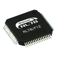
Renesas RL78/I1D Manuals
Manuals and User Guides for Renesas RL78/I1D. We have
6
Renesas RL78/I1D manuals available for free PDF download: User Manual, Application Note
Renesas RL78/I1D User Manual (63 pages)
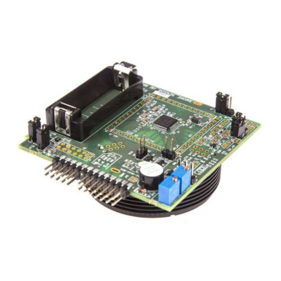
detector boards kit
Brand:
Renesas
| Category:
Microcontrollers
| Size: 2 MB
Table of Contents
Revision History
1
General Precautions in the Handling of MPU/MCU Products
2
Table of Contents
2
1 Hardware Overview
5
2 Detector Application Brief Explanation
5
Glass Break Detector Board Design Explanation
5
CO Detector Design Explanation
6
Motion Detector Design Explanation
8
Smoke Detector Design Explanation
9
3 Boards Layout
10
Glass Break Detector Board Layout
10
CO Detector Board Layout
11
Motion Detector Board Layout
13
Smoke Detector Board Layout
15
4 Content of the CD-ROM
17
5 Board Description
19
Glass Break Detector Board
19
Oscillators
20
Description of Jumper J
20
Description of Potentiometer JP
21
Buzzer
21
Description of Push Button
21
Battery Place Holder
22
Microcontroller RL78/I1D
22
Description of PMOD Connector J9
24
Description of Board Edge Connectors CN01 and CN02
24
CO Detector Board
25
Oscillators
26
Description of Jumper J
26
Description of Potentiometer JP
27
Buzzer
27
Description of Push Button
27
Battery Place Holder
28
Microcontroller RL78/I1D
28
Description of PMOD Connector J9
30
Description of Board Edge Connectors CN01 and CN02
30
Motion Detector Board
31
Oscillators
32
Description of Jumper J
32
Description of Potentiometer JP
33
Buzzer
34
Description of Push Button
34
Battery Place Holder
34
Microcontroller RL78/I1D
34
Description of PMOD Connector J9
36
Description of Board Edge Connectors CN01 and CN02
36
Smoke Detector Board
37
Sensor Connection
38
Oscillators
38
Description of Jumper J
38
Description of Potentiometer JP
39
Buzzer
39
Description of Push Button
39
Battery Place Holder
40
Microcontroller RL78/I1D
40
Description of PMOD Connector J9
42
Description of Board Edge Connectors CN01 and CN02
42
6 Theory of Operation
43
Glass Break Detector Theory of Operation
43
Analog Front End Circuit of Glass Break Detector
43
Mcu/Digital System and Maintain Low Current Drain for Long Battery Life
44
CO Detector Theory of Operation
44
Analog Front End Circuit of CO Detector
44
Mcu/Digital System and Maintain Low Current Drain for Long Battery Life
45
Motion Detector Theory of Operation
46
Analog Front End Circuit of Motion Detector
46
Mcu/Digital System and Maintain Low Current Drain for Long Battery Life
47
Smoke Detector Theory of Operation
47
Analog Front End Circuit of Smoke Detector
47
Mcu/Digital System and Maintain Low Current Drain for Long Battery Life
49
7 How to Start the Boards for Battery Operation
49
Glass Break Detector Demonstration Using Battery
49
CO Detector Demonstration Using Battery
49
Motion Detector Demonstration Using Battery
49
Smoke Detector Demonstration Using Battery
50
8 How to Start the Boards with IAR
50
9 Notes and Comments about Board Operation
56
Glass Break Detector Operation
56
Glass Break Sensor Testing Results
56
Glass Break Sensor Current Consumption Results
56
CO Sensor Operation
57
CO Sensor Testing Results
57
CO Sensor Current Consumption Results
57
CO Sensor Calibration Method
58
Motion Detector Operation
59
Motion Detector Testing Results
59
Motion Detector Current Consumption Results
59
Smoke Sensor Operation
59
Smoke Detector Testing Results
59
Smoke Detector Current Consumption Results
59
10 Support
60
Advertisement
Renesas RL78/I1D User Manual (59 pages)
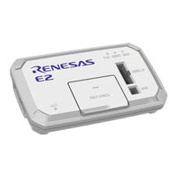
Emulator
Brand:
Renesas
| Category:
Computer Hardware
| Size: 1 MB
Table of Contents
Table of Contents
4
Overview
7
Overview of E1/E20/E2 Emulator and E2 Emulator Lite
7
Note on Using E20
7
Configuration of E1/E20/E2/E2 Lite Manuals
8
Supported Devices
9
Overview of the Specifications of the External Trigger Input and Output
11
Assignments of the External Trigger Input and Output Pins
11
Specifications of the External Trigger Inputs and Outputs
12
Designing the User System
13
Connecting the E1/E20/E2/E2 Lite to the User System
13
Installing the Connector on the User System
13
Connecting the User System Interface Cable to the 14-Pin Connector
13
Pin Assignments of the Connector on the User System
17
14-Pin Connector Specifications
17
Recommended Circuits between the Connector and the MCU
19
Connection between the 14-Pin Connector and the RL78 Family Mcus in General
19
Connection between the 14-Pin Connector and the RL78 Family Mcus
21
And the 20- and 24-Pin Versions of the RL78/G12)
21
Connection between the 14-Pin Connector and the RL78 Family MCU (Only the RL78/I1C)
22
Notes on Connection
25
RESET# Pin
25
TOOL0 Pin
28
Gnd
29
VDD
29
Internal Circuits of the Emulator
31
Internal Circuits of the E1 (When the RL78 Family Is Connected)
31
Internal Circuits of the E20 (When the RL78 Family Is Connected)
32
Internal Circuits of the E2 (When the RL78 Family Is Connected)
33
Internal Circuits of the E2 Lite (When the RL78 Family Is Connected)
35
Notes on Designing the User System
36
Isolator for the E1
36
Small Connector Conversion Adapter for the E1
36
Notes on Usage
38
Turning the Power On/Off
38
When a Separate Power Supply Is Used for the User System
38
When Power Is Supplied to the User System from the Emulator (E1/E2/E2 Lite Only)
39
Power Supply Function of the E1/E2/E2 Lite
39
MCU Resources to be Occupied
40
Securing an Area for the Debugging Monitor Program
41
Securing a Stack Area for Debugging
42
Setting an On-Chip Debugging Option Byte
43
Setting a Security ID
44
Setting a Serial Programming Security ID
45
Reset
46
Operation after a Reset
46
SP Value after a Reset
46
Flash Memory
46
Flash Memory Programming by Self-Programming
46
Operation for Voltages and Flash Operation Modes Not Permitting Flash Memory Rewriting
47
Gdidis
47
RESET# Multiplexed Pin
47
Mcus that Are Used in Debugging
48
Usage in Mass-Production
48
Standalone Operation
48
Final Evaluation of the User Program
48
Debug Functions
49
Stepped Execution
49
Go to Here]
49
Debugging in Standby Mode
49
Pseudo-Real-Time RAM Monitor Function or Pseudo-Dynamic Memory Modification Function
50
Start/Stop Functions
50
Emulation of Flash Memory CRC Accumulator Function
51
Break Function
51
Setting and Deleting Events During User Program Execution
51
Trace Function
51
Battery Backup Function
51
RAM-ECC Function
51
Extended Functions of the E2
52
Points for Caution on Using the Rl78/G2X
52
Points for Caution on Using the Rl78/F2X
54
Note on Self-Programming for Flash-Memory
56
State of High-Speed on Chip Oscillator During On-Chip Debugging
56
Setting of Download Mode (RL78/FGIC[RAJ240100])
56
Renesas RL78/I1D User Manual (58 pages)
E1/E20/E2 Emulator, E2 Emulator Lite
Brand:
Renesas
| Category:
Computer Hardware
| Size: 0 MB
Table of Contents
Table of Contents
4
Overview
7
Overview of E1/E20/E2 Emulator and E2 Emulator Lite
7
Note on Using E20
7
Configuration of E1/E20/E2/E2 Lite Manuals
8
Supported Devices
9
Overview of the Specifications of the External Trigger Input and Output
11
Assignments of the External Trigger Input and Output Pins
11
Specifications of the External Trigger Inputs and Outputs
12
Designing the User System
13
Connecting the E1/E20/E2/E2 Lite to the User System
13
Installing the Connector on the User System
13
Connecting the User System Interface Cable to the 14-Pin Connector
13
Pin Assignments of the Connector on the User System
17
14-Pin Connector Specifications
17
Recommended Circuits between the Connector and the MCU
19
Connection between the 14-Pin Connector and the RL78 Family Mcus in General
19
Connection between the 14-Pin Connector and the RL78 Family Mcus (Only the RL78/G11 and the 20- and 24-Pin Versions of the RL78/G12)
21
Connection between the 14-Pin Connector and the RL78 Family MCU (Only the RL78/I1C)
22
Notes on Connection
25
RESET# Pin
25
TOOL0 Pin
28
Gnd
29
VDD
29
Internal Circuits of the Emulator
31
Internal Circuits of the E1 (When the RL78 Family Is Connected)
31
Internal Circuits of the E20 (When the RL78 Family Is Connected)
32
Internal Circuits of the E2 (When the RL78 Family Is Connected)
33
Internal Circuits of the E2 Lite (When the RL78 Family Is Connected)
35
Notes on Designing the User System
36
Isolator for the E1
36
Small Connector Conversion Adapter for the E1
36
Notes on Usage
38
Turning the Power On/Off
38
When a Separate Power Supply Is Used for the User System
38
When Power Is Supplied to the User System from the Emulator (E1/E2/E2 Lite Only)
39
Power Supply Function of the E1/E2/E2 Lite
39
MCU Resources to be Occupied
40
Securing an Area for the Debugging Monitor Program
41
Securing a Stack Area for Debugging
42
Setting an On-Chip Debugging Option Byte
43
Setting a Security ID
44
Setting a Serial Programming Security ID
45
Reset
46
Operation after a Reset
46
SP Value after a Reset
46
Flash Memory
46
Flash Memory Programming by Self-Programming
46
Operation for Voltages and Flash Operation Modes Not Permitting Flash Memory Rewriting
47
Gdidis
47
RESET# Multiplexed Pin
47
Mcus that Are Used in Debugging
48
Usage in Mass-Production
48
Standalone Operation
48
Final Evaluation of the User Program
48
Debug Functions
49
Stepped Execution
49
Go to Here]
49
Debugging in Standby Mode
49
Pseudo-Real-Time RAM Monitor Function or Pseudo-Dynamic Memory Modification Function
50
Start/Stop Functions
50
Emulation of Flash Memory CRC Accumulator Function
51
Break Function
51
Setting and Deleting Events During User Program Execution
51
Trace Function
51
Battery Backup Function
51
RAM-ECC Function
51
Extended Functions of the E2
52
Points for Caution on Using the RL78/G23
52
Points for Caution on Using the RL78/F24
54
Advertisement
Renesas RL78/I1D User Manual (55 pages)
Brand:
Renesas
| Category:
Computer Hardware
| Size: 0 MB
Table of Contents
Table of Contents
4
1 Overview
7
Overview of E1/E20/E2 Emulator and E2 Emulator Lite
7
Note on Using E20
7
Configuration of E1/E20/E2/E2 Lite Manuals
8
Supported Devices
9
Overview of the Specifications of the External Trigger Input and Output
11
Assignments of the External Trigger Input and Output Pins
11
Specifications of the External Trigger Inputs and Outputs
12
2 Designing the User System
13
Connecting the E1/E20/E2/E2 Lite to the User System
13
Installing the Connector on the User System
13
Connecting the User System Interface Cable to the 14-Pin Connector
13
Pin Assignments of the Connector on the User System
17
14-Pin Connector Specifications
17
Recommended Circuits between the Connector and the MCU
19
Connection between the 14-Pin Connector and the RL78 Family Mcus in General
19
Connection between the 14-Pin Connector and the RL78 Family Mcus (Only the RL78/G11 and the 20- and 24-Pin Versions of the RL78/G12)
21
Connection between the 14-Pin Connector and the RL78 Family MCU (Only the RL78/I1C)
22
Notes on Connection
25
RESET# Pin
25
TOOL0 Pin
28
Gnd
29
VDD
29
Internal Circuits of the Emulator
31
Internal Circuits of the E1 (When the RL78 Family Is Connected)
31
Internal Circuits of the E20 (When the RL78 Family Is Connected)
32
Internal Circuits of the E2 (When the RL78 Family Is Connected)
33
Internal Circuits of the E2 Lite (When the RL78 Family Is Connected)
35
Notes on Designing the User System
36
Isolator for the E1
36
Small Connector Conversion Adapter for the E1
36
3 Notes on Usage
38
Turning the Power On/Off
38
When a Separate Power Supply Is Used for the User System
38
When Power Is Supplied to the User System from the Emulator (E1/E2/E2 Lite Only)
39
Power Supply Function of the E1/E2/E2 Lite
39
MCU Resources to be Occupied
40
Securing an Area for the Debugging Monitor Program
41
Securing a Stack Area for Debugging
42
Setting an On-Chip Debugging Option Byte
43
Setting a Security ID
44
Reset
45
Operation after a Reset
45
SP Value after a Reset
45
Flash Memory
45
Flash Memory Programming by Self-Programming
45
Operation for Voltages and Flash Operation Modes Not Permitting Flash Memory Rewriting
46
Gdidis
46
RESET# Multiplexed Pin
46
Mcus that Are Used in Debugging
47
Usage in Mass-Production
47
Standalone Operation
47
Final Evaluation of the User Program
47
Debug Functions
48
Stepped Execution
48
Go to Here]
48
Debugging in Standby Mode
48
Pseudo-Real-Time RAM Monitor Function or Pseudo-Dynamic Memory Modification Function
49
Start/Stop Functions
49
Emulation of Flash Memory CRC Accumulator Function
50
Break Function
50
Setting and Deleting Events During User Program Execution
50
Trace Function
50
3.10.10 Battery Backup Function
50
3.10.11 RAM-ECC Function
50
3.10.12 Extended Functions of the E2
51
3.10.13 Points for Caution on Using the RL78/G23
51
Renesas RL78/I1D Application Note (45 pages)
Brand:
Renesas
| Category:
Computer Hardware
| Size: 1 MB
Table of Contents
Table of Contents
9
The Main User Initialization
10
INTP0 Interrupt Enable Processing
10
12-Bit Interval Timer Start Processing
10
Clock Output Start Processing
10
A/D Conversion Operation Start Processing
10
A/D Converter Stop Processing
11
The Flash Operation State Is Switched to the LV Mode
11
The Flash Operation State Is Switched to the HS Mode
11
The Flash Operation State Is Switched to the LP Mode
12
A/D Conversion Complete Interrupt Processing
12
External Interrupt Processing
12
12-Bit Interval Timer Interrupt Processing
13
Outline
13
Renesas RL78/I1D User Manual (3 pages)
Target board
Brand:
Renesas
| Category:
Computer Hardware
| Size: 0 MB
Table of Contents
RL78/I1D Target Board (RTE5117GC0TGB00000R) Features
1
Hardware Specifications
1
Dimensions and Parts Layout
1
Notes on Use
1
When a Capacitor Is Mounted in an Analog Input Terminal
2
Advertisement
Related Products
Renesas RL78/I1A
Renesas RL78/I1C
Renesas RL78/G13
Renesas RL78/G10
Renesas rl78/g1g
Renesas RL78/G1H
Renesas RL78/F13
Renesas RL78/G23-128p
Renesas RL78/G1M
Renesas RL78/G1P
Renesas Categories
Computer Hardware
Motherboard
Microcontrollers
Adapter
Switch
More Renesas Manuals
Login
Sign In
OR
Sign in with Facebook
Sign in with Google
Upload manual
Upload from disk
Upload from URL