Sign In
Upload
Manuals
Brands
Regency Fireplace Products Manuals
Indoor Fireplace
City Series
Regency Fireplace Products City Series Manuals
Manuals and User Guides for Regency Fireplace Products City Series. We have
8
Regency Fireplace Products City Series manuals available for free PDF download: Owners & Installation Manual, Owners And Installation Manual, Manual
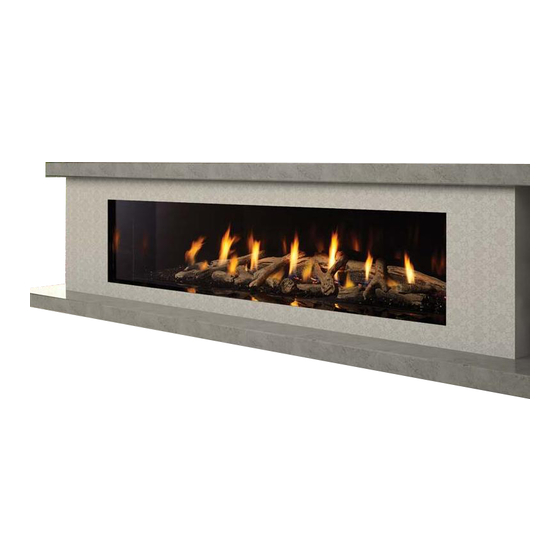
Regency Fireplace Products City Series Owners & Installation Manual (132 pages)
Brand:
Regency Fireplace Products
| Category:
Indoor Fireplace
| Size: 16 MB
Table of Contents
Table of Contents
5
Copy of Safety Decal
7
Decal Location
7
Important Message
9
Before You Start
9
First Fire
10
Normal Operating Sounds of Gas Appliances
10
Lighting Procedure
11
Shutdown Procedure
11
Copy of the Lighting Plate Instructions
12
Proflame II Remote Control Operating Instructions
13
Maintenance Instructions
17
General Vent Maintenance
17
Log Replacement
17
Glass
17
Glass Replacement
17
Replacement Glass Part Numbers
17
Installer's Information
18
Dimensions
18
Gas Connection - Bottom of Unit
19
Gas/Electrical Connections - Side of Unit
19
Gas Connection
19
Electrical Connection
19
General Safety Information
20
Installation Checklist
20
Heatwave Duct System - Optional Kit
20
Locating Your Gas Fireplace
21
Unit Assembly Prior to Installation
22
Installation - General
24
Chase Enclosure
24
Clearances - Flush Installation
25
Flush Installation Examples (Ventilation Openings)
26
Clearances - Bench Installation
29
Mantel Clearances
33
Mantel Leg Clearances
34
Framing Dimensions
35
Chase Vent Installation (White Front) (Part # 686-991)
36
Wall Board/Drywall Installation
37
No Screw Zones
37
Framing and Finishing Inset Installations
38
Finishing
41
Wall Mount on / off Switch and Battery Holder Installation
42
LP Conversion Instructions
43
NG System Data
45
LP System Data
45
High Elevation
45
Gas Line Installation
45
Pilot Adjustment
45
Gas Pipe Pressure Testing
45
885 S.I.T. Valve Description
45
Exterior Vent Termination Locations
46
Installation-Non Power Vent
47
5" X 8" (127 MM X 203 MM) Rigid Pipe Cross Reference Chart (Non Power Vent)
47
Vent Restrictor Position
49
Venting Introduction
50
Venting Arrangement for Horizontal Terminations (Rigid and Flex)
50
Horizontal Terminations - Flex Vent 5" X 8" (127 MM X 203 MM)
51
Horizontal Terminations - Rigid Pipe 5" X 8" (127 MM X 203 MM)
52
Venting Arrangement for Vertical Terminations - 5" X 8" (127 MM X 203 MM) Rigid and Flex Pipe
54
Vertical Terminations - 5" X 8" (127 MM X 203 MM) Rigid Pipe
55
Vertical Terminations - 5" X 8" - Rigid or Flex Pipe
56
Vertical Terminations - Vertical Flex Vent Kit (Part #946-772)
57
Vertical Flue Extension Kit (Part # 946-769)
59
Ceiling Firestop / Firestop Spacer (Part # 946-770)
60
Wiring Diagram - Non Power Vent
61
Wiring the Unit (120 Volt Power Supply)
62
Installation-Power Vent
64
Venting Introduction - Power Vent
64
4"X 6-5/8" (102 MMX 168 MM) Rigid Pipe Cross Reference Chart
65
Horizontal Terminations - Inline Horizontal Vent Chart
67
Vent Restrictor Position
67
Horizontal Terminations - End of Line Horizontal Vent Chart
68
Vent Restrictor Position
68
Horizontal Terminations - Inline Power Vent - 4" X 6-5/8" Flex Vent
69
Horizontal Terminations - Inline Power Vent - 4" X 6-5/8" Rigid Pipe
70
Horizontal Terminations - End of Line Power Vent - Rigid Pipe 4" X 6-5/8" (102 MM X 168 MM)
71
Power Vent Installation - End of Line Power Vent - Flex Pipe
72
Horizontal Termination - 4" X 6-5/8" (102 MM X 168 MM) Venting (Rigid Vent Systems)
73
Venting Arrangement for Vertical Terminations-Inline Power Vent
74
Vertical Inline Power Vent Terminations - Rigid Pipe
75
Vertical Terminations - Rigid Pipe 4" X 6-5/8" (102 MM X 168 MM)
76
Vertical Terminations - Flex Pipe
77
Inline Power Vent Dimensions
78
Gas Power Vent Installation - Framing- Inline Power Vent Terminations
79
Power Vent Terminal Installation-Inline Power Vent Terminations
80
Gas Power Vent Installation Clearance Requirements Inline Power Vent Terminations
81
Horizontal Termination-End of Line Power Vent - 4" X 6-5/8" (102 MM X 168 MM) Rigid Venting
82
Horizontal Termination-End of Line Power Vent - 4" X 6-5/8" (102 MM X 168 MM) Flex Venting
83
Vertical Inline Power Vent Terminations - Rigid Pipe
84
Vertical Inline Power Vent Terminations - Flex Pipe (Part # 946-755)
85
Vertical Inline Power Vent Terminations - Flex Pipe
86
Vertical Flue Extension Kit - Horizontal Power Vent Kit
87
Top Vent Reducer Installation - 5" X 8" (127 MM X 203 MM) to 4" X 6-5/8" (102 MM X 168 MM) (Part # 946-758)
88
Ceiling Firestop/Firestop Spacer (Part 946-757)
88
Gas Power Vent Install - Wiring the Inline Power Vent to the Unit
89
Horizontal Venting with Two 90 O Elbows
90
Horizontal Venting with Three
90
Gas Power Vent Installation - Wiring - End of Line Power Vent
90
Gas Power Vent Installation-Wiring-End of Line Power Vent
91
Gas Power Vent Installation--Wiring the Power Vent to the Unit
92
Wiring Diagram-Power Vent Application
94
Installation-Panels, Barriers, Faceplates
95
Inner Glass Panel (Firebox Glass) Installation / Removal
95
Glass Barrier Installation
97
Glass Barrier Adjustment
98
Inner Black Steel/Enamel Panel Installation (Part #450-907/450-908)
99
Inner Black Glass Panel Installation
101
Clean Trim Faceplate Installation
103
Installation-Media
104
Burner and Firebox Media Options
104
Optional Driftwood Log Set Installation
106
Maintenance
114
Maintenance Instructions
114
General Vent Maintenance
114
Log Replacement
114
Glass Gasket
114
Glass
114
Glass Replacement
114
Flame Pattern
114
Aeration Adjustment
115
Minimum Air Shutter Opening
115
Bulb Replacement
116
Valve Replacement
117
Gas Maintenance - Recommended Annual Routine
118
Parts Lists
119
Main Assembly
119
Accessories
121
Bottom Pressure Relief Gasket
121
Individual Glass Gasket Parts for Item # 25
121
Upper Glass Clamps
122
Lower Glass Clamps
122
Power Vent-End of Line (Part # 946-535)
123
Power Vent - Inline (Part # 666-945)
124
Warranty
126
Advertisement
Regency Fireplace Products City Series Owners & Installation Manual (124 pages)
Direct Vent Gas Power Vent Fireplace
Brand:
Regency Fireplace Products
| Category:
Indoor Fireplace
| Size: 23 MB
Table of Contents
Table of Contents
4
Copy Of Safety Decal
5
Gas Installation Checklist
6
Important Message
9
Before You Start
9
General Safety Information
10
Lighting Procedure
11
Shutdown Procedure
11
Copy Of The Lighting Plate Instructions
12
Proflame II Remote Control Operating Instructions
13
Outer Safety Glass Panel Installation/Removal
17
Outer Safety Glass Panel Installation/Removal
18
Inner Glass Panel (Firebox Glass) Installation/Removal
19
Maintenance Instructions
21
Log Replacement
21
Glass Gasket
21
Glass
21
Glass Replacement
21
Installer's Information
22
General Safety Information
23
Installation Checklist
23
Heatwave Duct System Optional Kit
23
Ventilation Openings
24
Chase Enclosure
25
Locating Your Gas Fireplace
26
Unit Assembly Prior To Installation
26
Clearances Cb40Epv
27
Optional Flush Chase Vent Installation
29
Optional Front Grill Installation
32
Optional Side Grill Installation
33
Optional Side Installation into Compact or Extended Framing Kit
33
Mantel Clearances Cb40Epv
34
Mantel Leg Clearances
34
Framing Dimensions Cb40Epv
35
Optional Framing Kit Installation Cb40Epv
36
Wall Board/Drywall Installation Cb40Epv
42
Framing And Finishing Inset Installations Cb40Epv
43
Extended Finish Cb40Epv
43
TV Recessed into Wall- Typical Installs
44
Maximum Tv Recess
44
Tv Flush With Hearth
44
Optional Wood Panel Kit Installation Cb40Epv
45
Optional Glass Panel Installation Cb40Epv
48
Optional Extended Hearth Kit Installation Cb40Epv
49
Optional Extended Hearth Panel Kit Installation Cb40Epv
51
Optional Compact Hearth Panel Kit Installation Cb40Epv
52
Extended Hearth Glass Top Installation
53
Exterior Vent Termination Locations
54
Cross Reference Chart
55
Wall Mount On / Off Switch Battery Holder Install
57
Venting Arrangements for Horizontal Terminations End of Line Horizontal Vent Chart
58
Venting Arrangements For Horizontal Terminations
58
Inline Horizontal Vent Chart
59
Venting Arrangement for Vertical Terminations-Inline Power Vent
60
Vertical Inline Power Vent Terminations Rigid Pipe
61
Venting Arrangements for Vertical Terminations Flex Pipe
62
Horizontal Terminations-Inline Power Vent -4" X 6-5/8" Flex Vent
63
Horizontal Terminations-Inline Power Vent
63
4" X 6-5/8" Rigid Pipe
64
Horizontal Terminations-End Of Line Power Vent
65
4" X 6-5/8" Rigid Pipe
65
Inline Power Vent Dimension
66
Gas Power Vent Installation-Framing
67
Inline Power Vent Terminations
67
Power Vent Terminal Installation-Inline Power Vent Terminations
68
Gas Power Vent Installation Clearance Requirements
69
Inline Power Vent Terminations
69
Unit Installation with Horizontal Termination-End of Line Power Vent-4" X 6-5/8" Rigid Venting
70
Unit Installation with Horizontal Termination-End of Line Power Vent-4" X 6-5/8" Flex Venting
71
Verical Inline Power Vent Terminations-Rigid Pipe
72
Verical Inline Power Vent Terminations-Flex Pipe
73
Vertical Flue Extension Kit-Horizontal Power Vent Kit
75
Celing Firestop / Firestop Spacer
76
Gas Power Vent Installation-Wiring The Power Vent To Unit
77
Gas Power Vent Install-Wiring-End Of Line Power Vent
78
Gas Power Vent Installation-Wiring The Power Vent To
80
The Unit- Access Panel Removal
80
System Data
83
High Elevation
83
Gas Line Installation
83
Pilot Adjustment
83
Gas Pipe Pressure Testing
83
885 S.I.T. Valve Description
83
Wiring Diagram - Power Vent Application
84
Inner Glass Panel (Firebox Glass) Installation
85
Outer Safety Glass Panel (Barrier Glass) Installation
87
Lp Conversion Instructions
89
Cb40Epv Painted Panel Installation (Inner/Outer Panels)
91
Cb40Epv Glass Panel Installation
92
Cb40Epv Enamel Panel Installation
93
Burner And Firebox Media Options
94
Optional Driftwood Log Set Installation
95
Optional Birchwood Log Set Installation
97
Optional Splitwood Log Set Installation
99
Tv Kit Installation
101
First Fire
103
Normal Operating Sounds Of Gas Appliances
103
Aeration Adjustment
103
Maintenance Instructions
104
General Vent Instructions
104
Log Replacement
104
Glass Gasket
104
Glass
104
Glass Replacement
104
Bulb Replacement
105
Valve Replacement
106
End of Line Power Vent Maintenance - External Power Vent Access
107
Internal Power Vent Access
108
Power Vent Maintenance - External Power Vent Access
109
Inline Power Vent
109
Gas Maintenance
110
Cb40Epv Main Assembly
111
Cb40Epv Accessories
112
Power Vent - End Of Line
114
Power Vent - Inline
115
Warranty
116
Regency Fireplace Products City Series Owners And Installation Manual (108 pages)
Brand:
Regency Fireplace Products
| Category:
Indoor Fireplace
| Size: 11 MB
Table of Contents
Table of Contents
4
Copy Of Safety Decal
5
Dimensions
6
Gas Connection - Back Of Unit
7
Gas Connection - Bottom Of Unit
7
Gas Connection - Side Of Unit
7
Gas Installation Checklist
8
Important Message
10
Before You Start
10
First Fire
11
Normal Operating Sounds Of Gas Appliances
11
Lighting Procedure
12
Shutdown Procedure
12
Copy Of The Lighting Plate Instructions
13
Proflame II Remote Control Operating Instructions
14
Glass Barrier Removal
18
Inner Glass Panel (Firebox Glass) Installation / Removal
19
Optional Barrier Glass Stoppers Installation / Removal
21
Bulb Replacement
22
Maintenance Instructions
23
Log Replacement
23
Glass
23
Glass Replacement
23
Back Up Battery System
23
General Safety Information
25
Installation Checklist
25
Heatwave Duct System Optional Kit
25
Locating Your Gas Fireplace
26
Unit Assembly Prior To Installation
27
Clearances
29
Mantel Clearances
30
Mantel Leg Clearances
30
Framing Dimensions
31
Electrical Connection - Bottom Of Unit
32
Electrical Connection - Side Of Unit
32
Chase Vent Installation
33
Extended View Panel Installation
36
Wall Board/Drywall Installation
38
No Screw Zones
38
Framing And Finishing Inset Installations
39
Drywall Lip - Bottom And Sides (Optional)
39
Typical Installations
40
Flush Install
40
Recessed Install
40
Typical Installations
41
Maximum Tv Recess
41
Flush Tv With Hearth
41
Finishing
42
Chase Venting
43
Exterior Vent Termination Locations
44
5" X 8" Rigid Pipe Cross Reference Chart
45
Wall Mount On / Off Switch And Battery Holer Installation
47
Required For All Installations
47
Vent Restrictor Position
48
Horizontal Terminations - Flex Vent 5" X 8
49
Horizontal Terminations - Rigid Pipe 5" X 8
50
Horizontal Terminations - Rigid Pipe 5" X 8
51
Horizontal Venting with Two (2) 90 O Elbows
51
Horizontal Venting with Three (3) 90 O Elbows
51
Venting Introduction
52
Venting Arrangement For Horizontal Terminations
52
Horizontal Termination 5" X 8" Venting (Flex Vent Systems)
53
Horizontal Termination - 5" X 8" Venting (Rigid Vent Systems)
54
Vertical Terminations - Rigid/Flex Pipe 5" X 8
55
Vertical Terminations - Rigid/Flex Pipe 5" X 8
56
Venting Arrangement for Vertical Terminations - Straight Vertical Venting And/Or with a Max. of Two (2)
57
Elbows )
57
Vertical Termination (Rigid Vent Systems)
58
Vertical Terminations - Vertical Flex Vent Kit (Part #946-772)
59
Vertical Flex Extension Kit (Part # 946-769)
61
Ceiling Firestop / Firestop Spacer (Part # 946-770)
62
Heatwave Deflector + Heatwave Venting Installation
63
System Data
64
High Elevation
64
Gas Line Installation
64
Pilot Adjustment
64
Gas Pipe Pressure Testing
64
885 S.I.T. Valve Description
64
Wiring The Unit
65
Wiring Diagrams
66
Inner Glass Panel (Firebox Glass) Installation / Removal
67
Optional Barrier Glass Stoppers Installation / Removal
69
Lp Conversion Instructions
70
Bulb Replacement
72
Cv72E Painted Panel Installation
73
Inner Panels
73
Outer Panels
73
Enamel Panel Installation
74
Glass Panel Installation
75
Burner And Firebox Media Options
77
Optional Driftwood Log Set Installation
78
Optional Birch Wood Log Set Installation
82
Optional Splitwood Log Set Installation
86
Glass Barrier Installation
90
Glass Barrier Adjustment
91
Aeration Adjustment
92
Minimum Air Shutter Opening
92
Maintenance Instructions
93
Flame Pattern
93
Glass
93
Glass Gasket
93
Glass Replacement
93
Log Replacement
93
Maintenance Instructions
93
Valve Replacement
94
Gas Maintenance - Recommended Annual Routine
95
Parts List
96
Main Assembly
96
Main Assembly
97
Accessories
98
Warranty
100
Advertisement
Regency Fireplace Products City Series Owners & Installation Manual (108 pages)
Direct Vent Gas Power Vent Fireplace, Single sided
Brand:
Regency Fireplace Products
| Category:
Indoor Fireplace
| Size: 17 MB
Table of Contents
Table of Contents
4
Copy Of Safety Decal
5
Unit Dimensions
6
Gas Installation Checklist
7
Important Message
9
Before You Start
9
General Safety Information
10
Lighting Procedure
11
Shutdown Procedure
11
Copy Of The Lighting Plate Instructions
12
Proflame II Remote Control Operating Instructions
13
Inner Glass Panel (Firebox Glass) Installation
17
Outer Safety Glass Panel (Barrier Glass) Installation
18
Maintenance Instructions
19
General Vent Maintenance
19
Log Replacement
19
Glass Gasket
19
Glass
19
Glass Replacement
19
Installer's Information
20
Locating Your Gas Fireplace
21
Unit Assembly Prior To Installation
21
General Safety Information
23
Installation Checklist
23
Heatwave Duct System Optional Kit
23
Ventilation Openings
24
Chase Enclosure
25
Clearances Cv40Epv
27
Optional Flush Front Chase Vent Installation
28
Optional Front Grill Installation - Part #656-991
30
Optional Side Grill Installation - Part #656-992
30
Mantel Clearances Cv40Epv
31
Mantel Leg Clearances
31
Framing Dimensions Cv40Epv
32
Wall Board/Drywall Installation
33
Framing And Finishing Inset Installations Cv40Epv
34
Tv Recessed Into Wall
35
Maximum Tv Recess
35
Tv Flush With Hearth
35
Exterior Vent Termination Locations
36
4"X 6-5/8" Rigid Pipe Cross Reference Chart
37
Venting Arrangements for Horizontal Terminations End of Line Horizontal Vent Chart
39
Venting Arrangements for Horizontal Terminations Inline Horizontal Vent Chart
40
Venting Arrangement for Vertical Terminations-Inline Power Vent
41
Vertical Inline Power Vent Terminations - Rigid Pipe
42
Venting Arrangements for Vertical Terminations -Flex Pipe
43
Horizontal Terminations-Inline Power Vent
44
4" X 6-5/8" Flex Vent
44
Horizontal Terminations - Inline Power Vent -4" X 6-5/8" Rigid Pipe
45
Horizontal Terminations - End Of Line Power Vent
46
4" X 6-5/8" Rigid Pipe
46
Inline Power Vent Dimensions
47
Gas Power Vent Installation - Framing Inline Power Vent Terminations
48
Power Vent Terminal Installation - Inline Power Vent Terminations
49
Gas Power Vent Installation Clearance Requirements Inline Power Vent Terminations
50
Unit Installation with Horizontal Termination - End of Line Power Vent-4" X 6-5/8" Rigid Venting
51
Unit Installation with Horizontal Termination - End of Line Power Vent-4" X 6-5/8" Flex Venting
52
Verical Inline Power Vent Terminations - Rigid Pipe
53
Verical Inline Power Vent Terminations - Flex Pipe
54
Vertical Flue Extension Kit-Horizontal Power Vent Kit
56
Ceiling Firestop/Firestop Spacer
57
Gas Power Vent Install - Wiring Power Vent To Unit
58
Gas Power Vent Install-Wiring End of Line Power Vent 5 9 Gas Power Vent Install-Wiring Power Vent to Unit
61
System Data
64
High Elevation
64
Gas Line Installation
64
Pilot Adjustment
64
Gas Pipe Pressure Testing
64
885 S.I.T. Valve Description
64
Wiring Diagram - Power Vent Application
65
Inner Glass Panel (Firebox Glass) Installation
66
Outer Safety Glass Panel (Barrier Glass) Installation
67
Lp Conversion Instructions
68
Wall Mount On/Off Switch & Battery Holder Install
70
Clean Trim Faceplate Installation
71
Cv40Epv Panel Install (Painted, Glass & Enamel)
72
Extended View Panel Installation
75
Burner And Firebox Media Options
77
Optional Driftwood Log Set Installation
78
Optional Birchwood Log Set Installation
80
Optional Splitwood Log Set Installation
82
Tv Kit Installation
84
First Fire
86
Normal Operating Sounds Of Gas Appliances
86
Aeration Adjustment
86
Maintenance Instructions
87
Log Replacement
87
Glass Gasket
87
Glass
87
Glass Replacement
87
Bulb Replacement
88
Valve Replacement
89
End of Line Power Vent Maintenance External Power Vent Access
90
Internal Power Vent Access
91
Power Vent Maintenance - External Power Vent Access Inline Power Vent
92
Gas Maintenance
93
Cv40Epv Main Assembly
94
Power Vent - End Of Line
97
Power Vent - Inline
98
Warranty
100
Regency Fireplace Products City Series Owners & Installation Manual (84 pages)
Zero Clearance Direct Vent Gas Fireplace, Single sided
Brand:
Regency Fireplace Products
| Category:
Indoor Fireplace
| Size: 12 MB
Table of Contents
Table of Contents
4
Copy of the Data Badge
5
Dimensions
6
Important Message
7
Before You Start
7
Owner's Information
7
General Safety Information
8
Lighting Procedure
9
Shutdown Procedure
9
Copy of the Lighting Plate Instructions
10
Proflame II Remote Control Operating Instructions
11
Temperature Indication Display
12
Room Thermostat (Transmitter Operation)
12
Smart Thermostat (Transmitter Operation)
13
Remote Dimmer Control (Light)
13
Fan Speed Control
13
Continuous Pilot/Intermittent Pilot (CPI/IPI) Selection
14
Proflame II Battery Holder Battery Replacement
15
Inner Glass Panel (Firebox Glass) Installation
16
Outer Safety Glass Panel (Barrier Glass) Installation / Removal
17
Maintenance Instructions
18
General Vent Maintenance
18
Log Replacement
18
Glass Gasket
18
Glass
18
Glass Replacement
18
Installer's Information
19
Locating Your Gas Fireplace
19
Unit Assembly Prior to Installation
19
Side and Back Standoff Assembly
19
Nailing Strips
19
Levelling Bolts
20
Access Panel Removal
20
Installation Checklist
21
Installation
22
Ventilation Openings
22
Chase Enclosure
23
Clearances
24
Mantel Clearances
25
Mantel Leg Clearances
25
Framing Dimensions
26
Chase Vent Installation
27
Optional Front Grill Installation
30
City Series
30
Wall Board/Plasterboard Installation
31
Framing and Finishing Inset Installations
32
TV Recessed into Wall
33
Maximum TV Recess
33
TV Flush with Hearth
33
Exterior Flue Termination Locations
34
Clearances
35
Wall Mount On/Off Switch and Battery
36
Vent Restrictor Position
37
Flueing Arrangements Horizontal Terminations
38
Flueing Introduction
39
Flueing Arrangement for Horizontal Terminations
39
Horizontal Terminations
40
Horizontal Terminations Rigid Pipe
41
Vertical Terminations
42
Flueing Arrangement for Vertical Terminations
43
Vertical Terminations
44
Unit Installation with Horizontal Termination
45
Dura-Vent Vertical Termination
47
Vertical Termination 102Mm X 175Mm Flueing - Vertical Flex Vent Kit
48
Vertical Flue Extension Kit
50
Ceiling Firestop/Firestop Spacer
50
System Data
51
High Elevation
51
Gas Line Installation
51
Pilot Adjustment
51
Gas Pipe Pressure Testing
51
885 S.I.T. Valve Description
51
Wiring Diagram
52
Optional Fan Ducting Kit Installation
53
General Information
53
Minimum Framing Clearances
53
Optional Fan Kit Installation
54
Fan Duct Entension Kit
55
Wiring Diagram
55
Inner Glass Panel (Firebox Glass) Installation
56
Outer Safety Glass Panel (Barrier Glass) Installation
57
Propane/Ulpg Conversion Instructions
58
Conversion from Ng to Lp/Ulpg
58
City Series
58
Painted Panel Installation
60
Outer Panels
60
Cv40E Enamel Panel Installation
61
Extended View Panel Installation
62
Burner and Firebox Media Options
64
Optional Driftwood Log Set Installation
65
Operating Instructions
67
First Fire
67
Normal Operating Sounds of Gas Appliances
67
Aeration Adjustment
67
Maintenance
68
Maintenance Instructions
68
General Vent Maintenance
68
Log Replacement
68
Glass Gasket
68
Glass
68
Glass Replacement
68
Bulb Replacement
69
Valve Replacement
70
Gas Appliance Maintenance
71
Parts List
72
Main Assembly
72
Warranty
74
Regency Fireplace Products City Series Owners & Installation Manual (87 pages)
Zero Clearance Direct Flue Gas Fireplace
Brand:
Regency Fireplace Products
| Category:
Indoor Fireplace
| Size: 17 MB
Table of Contents
Table of Contents
3
Owner's Information
4
Copy Of Data Badge
4
Dimensions
5
Before You Start
6
Important Message
6
General Safety Information
7
Lighting Procedure
8
Shutdown Procedure
8
Copy Of The Lighting Plate Instructions
9
Proflame II Remote Control Operating Instructions
10
Outer Safety Glass Panel Installation / Removal
14
Inner Glass Panel Installation / Removal
16
General Flue Maintenance
18
Glass
18
Glass Gasket
18
Glass Replacement
18
Log Replacement
18
Maintenance Instructions
18
Installer's Information
19
General Safety Information
19
Installation Checklist
19
Locating Your Gas Fireplace
20
Unit Assembly Prior To Installation
20
Installation
21
Clearances
21
Mantel Clearances
23
Mantel Leg Clearances
23
Framing Dimensions
24
Optional Framing Kit Installation
25
Chase Flue Installation
31
Chase Flueing
34
Optional Front Grill Installation
35
Optional Side Grill Installation
36
Wall Board/Plasterboard Installation
37
Framing And Finishing Inset Installations
38
Extended Finish (Walls Closed Off At Either End)
38
Tv Recessed Into Wall - Typical Installs
39
Maximum Tv Recess
39
Tv Flush With Hearth
39
Exterior Flue Termination Locations
40
Clearances
41
Wall Mount on / off Switch and Battery Holder Installation
42
Flue Restrictor Position
43
Flueing Arrangements Horizontal Terminations
44
Flueing Introduction
45
Flueing Arrangement For Horizontal Terminations
45
Horizontal Terminations
46
Vertical Terminations
48
Flueing Arrangement For Vertical Terminations
49
Vertical Terminations
50
Unit Installation With Horizontal Termination
51
Duravent Vertical Termination
53
Vertical Termination-102 MM X 175 MM Flueing
54
Vertical Flue Extension Kit
56
Ceiling Firestop / Firestop Spacer (Part #946-757)
56
System Data
57
High Elevation
57
Gas Line Installation
57
Pilot Adjustment
57
Gas Pipe Pressure Testing
57
885 S.I.T. Valve Description
57
Wiring Diagrams
58
Optional Fan Ducting Kit Installation
59
Fan Duct Extension Kit
61
Wiring Diagram
61
Inner Glass Panel (Firebox Glass) Installation / Removal
62
Outer Safety Glass Panel (Barrier Glass) Installation / Removal
64
Propane/Ulpg Conversion Instructions
66
Painted Panel Installation
68
Enamel Panel Installation
69
Burner And Firebox Media Options
70
Optional Driftwood Log Set Installation
71
Operating Instructions
73
First Fire
73
Normal Operating Sounds Of Gas Appliances
73
Aeration Adjustment
73
Maintenance
74
Maintenance Instructions
74
General Flue Maintenance
74
Log Replacement
74
Glass Gasket
74
Glass
74
Glass Replacement
74
Bulb Replacement
75
Valve Replacement
76
Main Assembly
77
Warranty
80
Regency Fireplace Products City Series Manual (33 pages)
Direct Vent Gas Fireplace
Brand:
Regency Fireplace Products
| Category:
Indoor Fireplace
| Size: 3 MB
Table of Contents
Gas Connection - Bottom of Unit
2
Gas Connection - Side of Unit
2
Mantel Clearances
8
Recessed Install
12
Horizontal Terminations
17
Flat Wall Installation
17
Horizontal Venting with Two (2)
19
Vertical Terminations
20
Vertical Termination
23
Installation
24
Vent Restrictor Position
30
Regency Fireplace Products City Series Manual (10 pages)
Brand:
Regency Fireplace Products
| Category:
Indoor Fireplace
| Size: 1 MB
Table of Contents
Clearances Cb72Epv
2
Mantel Clearances Cb72Epv
4
Mantel Leg Clearances
4
Framing Dimensions Cb72Epv
5
Venting Arrangements for Horizontal Terminations
6
Vent Restrictor Position
6
Horizontal Terminations
7
Gas Power Vent Installation Cb72Epv - Rigid Pipe
8
Advertisement
Related Products
Regency Fireplace Products CI1250 Alterra
Regency Fireplace Products CI1200 Alterra
Regency Fireplace Products CI2600
Regency Fireplace Products CI2700
Regency Fireplace Products Alterra CI1150
Regency Fireplace Products Alterra Ci1150-1
Regency Fireplace Products CB72EPV-NG
Regency Fireplace Products CF780
Regency Fireplace Products City Series CC40LE-LP12
Regency Fireplace Products City Series CC40RE-NG12
Regency Fireplace Products Categories
Indoor Fireplace
Wood stove
Stove
Fireplace Accessories
Outdoor Fireplace
More Regency Fireplace Products Manuals
Login
Sign In
OR
Sign in with Facebook
Sign in with Google
Upload manual
Upload from disk
Upload from URL