Parker Compax3S Manuals
Manuals and User Guides for Parker Compax3S. We have 6 Parker Compax3S manuals available for free PDF download: Operating Instructions Manual, Manual, Installation Manual, Quick Reference Manual
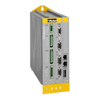
Parker Compax3S Operating Instructions Manual (398 pages)
Positioning via digital I/Os & Com port
Brand: Parker
|
Category: Servo Drives
|
Size: 20 MB
Table of Contents
Advertisement
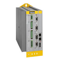

Parker Compax3S Installation Manual (44 pages)
Single-Axis Servo Drive/Controller/Single axis devices
Brand: Parker
|
Category: Controller
|
Size: 1 MB
Table of Contents
Advertisement


Parker Compax3S Manual (46 pages)
Brand: Parker
|
Category: Industrial Equipment
|
Size: 4 MB
Table of Contents

Advertisement