Sign In
Upload
Manuals
Brands
Paradyne Manuals
Network Hardware
COMSPHERE 3611
Paradyne COMSPHERE 3611 Network Hardware Manuals
Manuals and User Guides for Paradyne COMSPHERE 3611 Network Hardware. We have
1
Paradyne COMSPHERE 3611 Network Hardware manual available for free PDF download: Application Manual
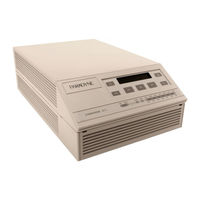
Paradyne COMSPHERE 3611 Application Manual (238 pages)
DATA SERVICE UNITS TIME DIVISION MULTIPLEXER, MULTICHANNEL MULTIPOINT, AND DIGITAL BRIDGE OPTIONS
Brand:
Paradyne
| Category:
Network Hardware
| Size: 2.45 MB
Table of Contents
Table of Contents
5
Comsphere 3600 Series Data Service Units
2
Important Safety Instructions
3
Table of Contents
5
Document Feedback
2
About this Guide
11
How to Use this Guide
11
Preface
11
Reference Documents
12
Related Documents
12
1 Overview
13
Standard Features
14
Optional Features
14
Models
18
Model 3610 DSU with TDM or MCMP
19
Model 3611 DSU with TDM or MCMP
20
DBM Types
21
Government Requirements
21
Equipment Warranty and Support
21
2 Model 3610 Installation
23
Overview
23
Hardware Straps
24
Model 3610 Tdm/Flex or Mcmp/Flex Switch Locations
25
Model 3610 TDM/DSD or MCMP/DSD Circuit Card Switch Locations
25
Changing Hardware Settings
26
Opening the DSU
26
Assembling/Disassembling the TDM or MCMP
27
Changing Tdm/Flex or Mcmp/Flex Interface Compatibility
28
Changing TDM/DSD or MCMP/DSD Interface Compatibility
29
Electrical Connection
30
Model 3610 DSU with TDM or MCMP
31
Network Diagnostic Connection
32
Software Configuration
32
Network and LADS Connections
33
DSU DTE Connection
33
Verification Testing
34
Dsu
35
Adding a Tdm/Flex or Mcmp/Flex to an Installed Model 3610 DSU
35
Getting Started
36
Disconnecting the DSU
36
Removing the DSU from Its Base
37
Installing a Tdm/Flex or Mcmp/Flex
37
Reassembling the Unit
38
3 Model 3611 Installation
39
Overview
39
Non-Modular TDM/MCMP Circuit Card Switch Locations
41
Hardware Straps
41
Software Configuration
42
Modular TDM/MCMP Circuit Card Switch Locations
42
Verification Testing
43
Adding a TDM or MCMP to an Installed Model 3611 DSU
44
Non-Modular TDM or MCMP Installation
47
COMSPHERE 3000 Series Carrier (Rear)
48
Modular TDM or MCMP Installation
49
Removing TDM or MCMP from an Installed Model 3611 DSU
51
4 Principles of Operation
53
Network Terminology
54
Point-To-Point Transmission
54
Multipoint Transmission
55
Overview
54
Modes of Operation
56
Basic Mode
56
Bridge Mode
56
MCMP Mode
56
TDM Mode
56
Functional Representation of Point-To-Point Multiplexing
57
Speed Characteristics
58
Asynchronous and Synchronous Sources
58
In-Band Framing and Underspeed Channel
58
TDM Architecture
59
TDM Architecture and Signal Flow
59
Time Division Multiplexing
57
Single-Port Point-To-Point Circuit with Nondisruptive Diagnostics
60
TDM Applications
60
Single-Port Async/Sync Support
60
Multipoint Async-Compatible Network
61
Point-To-Point Multiplexing
62
Diagnostic Path Extension
63
Digital Sharing
63
TDM Backbone Circuit with Extensions
63
TDM with Extended Circuit
63
Digital Sharing
64
Multiplexing and Digital Sharing
65
FEP Port Sharing
66
FEP Port Sharing
67
Case 1 – V.32 Backup for Subrate DDS
68
TDM Backup
68
Case 2 – V.32 Backup for High-Speed DSU
69
Case 3 – V.32 Backup for DSU with Extended Circuits
70
Case 4 – Switched 56 DBM Backup for DSU Operating at 56 Kbps or Less
71
Case 5 – Aggregate Switched Backup for TDM Circuits Configuration
72
Multichannel Multipoint
73
Typical Parallel Networks
73
Applications Combined on One DDS Multipoint Circuit with MCMP
74
Line and Channel Speeds
75
In-Band Secondary Channel Transport
75
Management Channel
75
MCMP Overhead Composition
75
Number of Tributaries
75
MCMP Architecture
76
MCMP Architecture and Signal Flow
76
Initialization
77
MCMP Applications
77
MCMP Operation
77
Network Modification
77
Switched-Carrier Emulation
77
Mcmp
78
MCMP with Digital Sharing
78
MCMP with Independent Channels
78
MCMP with FEP Port Sharing
79
MCMP Backup
80
Case 2 – Backing up the Channels to the most Important Tributary Location
81
Case 3 – Backing up One Complete Channel (Partial Backup)
82
Case 3 – Backing up One Complete Channel (Full Backup)
83
Case 4 – Backing up (up To) Three Channels Via the FEP Port-Sharing Feature
84
Digital Bridge/Dce Interface
85
Aggregate Switched Backup for MCMP Circuit Configuration
86
Digital Bridge
87
Multipoint with Digital Bridging
87
Maximum Bridging Capability – up to 20 Bridging Ports
88
Broadcasting Data through the Digital Bridge
89
Diagnostic Considerations
90
Multipoint Backup
90
Multipoint DDS Circuit in Partial Backup
91
Tributary Addressing Via DDS Connections
92
Multipoint Backup Addressing
92
Tributary Addressing Via Backup Connections
93
Multipoint Backup Architecture
94
Central-Site Bridging Architecture (9.6 Kbps) – Partial Backup in Effect
95
Central-Site Bridging Architecture (56 Kbps) – Inactive Digital Bridge
96
Central-Site Bridging Architecture (56 Kbps) – Active Digital Bridge
97
Central-Site DBM-Vs/Dbm-Ss/Dbm-Ds
97
DBM-V/DBM-S/DBM-D Dial on DTR Capability
98
Digital Bridge/Dbm-V/DBM-S/DBM-D - Switched LSD Operation
98
Digital Bridge/Dbm-V/DBM-S/DBM-D Interface
98
Setup - DSU Rate Equals DBM Rate
98
Tributary DSU Considerations
98
Automatic DDS Restoration
99
Manual DDS Restoration
99
Setup - DBM Rate Less than DSU Rate
99
LADS Operation
100
LADS Connection Distances
100
Bridged LADS
101
Point-To-Point LADS
101
Bridged LADS Operation
102
Bridged LADS Architecture and Signal Flow
103
Bridged LADS Architecture
103
NMS Control
104
Digital Bridge/Dsu Interface
104
SNA Diagnostic Interface
105
LPDA-2 Addressing
105
Assigning an Address to the Control DSU
105
Assigning an Address to the Tributary DSU
106
Sample Configuration and LPDA-2 Addressing
106
Dial Backup with LPDA-2 Configuration
107
Netview-Initiated Dial Backup
107
Multiplexing with TDM or MCMP
108
Multipoint Dial Backup
108
Multipoint Dial Backup with LPDA-2
108
Multiplexing with MCMP (LPDA-2 Monitoring)
109
Digital Sharing
110
Multiplexing with TDM (LPDA-2 Monitoring)
109
Digital Sharing in a Point-To-Point Circuit
110
Digital Sharing in a Multipoint Circuit
111
Digital Sharing in a TDM Circuit (LPDA-2 Monitoring)
112
Digital Sharing in an MCMP Circuit (LPDA-2 Monitoring)
113
5 Dsu Operations
115
Diagnostic Control Panels
116
Overview
116
Model 3611 DSU and TDM Faceplates
117
Status Indicators
117
DBM-V, DBM-S, and DBM-D Faceplates
118
TDM and MCMP Status Indicators (Model 3611 Only)
119
DSU with TDM or MCMP and DBM-V/DBM-S/DBM-D Status Indicators
120
Model 3611 DSU and MCMP Faceplates
118
Menu Structure
121
Menus and Mode of Operation
121
Local/Remote Menu Subbranches
121
Status Branch
122
Health and Status
123
Device Health and Status
123
Expanded Health and Status
123
DTE Lead Status Codes
124
Subnetwork Health and Status
124
DTE Status
124
Circuit Quality
125
Terminal Power
125
Backup Branch
126
Dbm/Dbm-V/Dbm-S/Dbm-D
126
Aggregate Switch
127
Bridge
127
Backup Branch Menu Selections
127
Test Branch
128
Abort
129
Device Test
129
Device Test
130
Loopback
131
Local Loopback
131
DTE Loopback
133
DTE Loopback on Port 2
133
Digital Loopback
134
Remote Digital Loopback
136
Bilateral Loopback
138
Digital Test
139
Digital Test
140
End-To-End Test
141
Digital Test Results
141
End-To-End Test Results
142
Bit Error Rate Test Results
143
Bit Error Rate Test
143
Bit Error Rate Tests in TDM or MCMP Mode
144
Configuration Branch
145
Lamp Test
145
Options
146
MUX Configuration Options
146
MUX Setup Option Set
147
Choosing Mode of Operation and Setting Configuration Options
149
Complete List of MUX Setup Configuration Options
150
Port Option Sets
151
Complete List of MUX Port Configuration Options
152
Port Speed Configuration Options
153
Poll List
154
Adding Self to Poll List
154
Acquiring the Poll List
155
Directory
155
Phone
156
Async Terminal
156
Directory Entry and Password Characters
156
Control Branch
157
Control Branch Menu Options
157
Transmitter Control
158
Leds
159
External Leads
160
Data Service Unit Menu
161
Configuration Worksheets
165
Pin Assignments
179
Time Division Multiplexer Connector Used with Non-Modular TDM
180
C-1 TDM Interface Cable (Feature Number 3600-F2-500)
180
Digital Bridge Connector Used with Non-Modular TDM/MCMP
183
C-2 Digital Bridge Interface Cable (Feature Number 3600-F2-501)
183
C-3 Pin Locations on the 60-Position High-Density Connector of the Non-Modular Carrier-Mounted TDM/MCMP Circuit Card
186
Model 3611 DSU
187
EIA-232-D/V.24 Connector (Port 1
188
Connector (Port 1)
189
C-5 V.35 Connector (Port 1)
189
Model 3610 (Ports 2 - 6) and Modular DSU 25-Pin V.35 Connector
191
C-6 6-Port Connector Module (Part Number 870-1700-0011)
192
EIA-232/V.24 TDM/MCMP Connector (Modular and Standalone - Ports 2 through 6
193
C-7 6-Port V.35 Interconnect Cable (Feature Number 3600-F3-500)
194
6-Port V.35 Interconnect Cable Connector
195
Advertisement
Advertisement
Related Products
Paradyne COMSPHERE 3610
Paradyne COMSPHERE 3550
Paradyne COMSPHERE 3551
Paradyne Jetstream CPX-1000
Paradyne CSU, DSU
Paradyne Comsphere
Paradyne COMSPHERE DUALFLOW 3615
Paradyne COMSPHERE 3000 Series
Paradyne COMSPHERE 3825PLUS
Paradyne COMSPHERE 3821Plus
Paradyne Categories
Network Hardware
Modem
Network Router
Adapter
Network Card
More Paradyne Manuals
Login
Sign In
OR
Sign in with Facebook
Sign in with Google
Upload manual
Upload from disk
Upload from URL