Sign In
Upload
Manuals
Brands
Omron Manuals
Robotics
TM5 Regular Payload Series
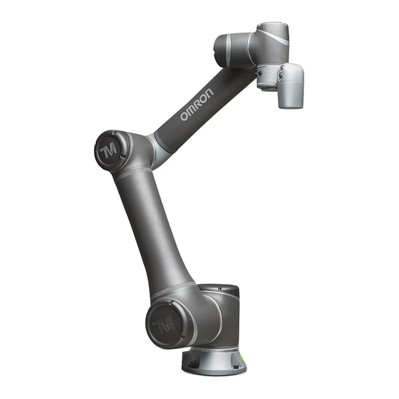
Omron TM5 Regular Payload Series Manuals
Manuals and User Guides for Omron TM5 Regular Payload Series. We have
2
Omron TM5 Regular Payload Series manuals available for free PDF download: Hardware Installation Manual
Omron TM5 Regular Payload Series Hardware Installation Manual (72 pages)
Brand:
Omron
| Category:
Robotics
| Size: 13 MB
Table of Contents
Table of Contents
3
Revision History Table
8
Product Dscription
9
Product Description
9
How Can I Get Help
9
Table 1: Manual Title & Description
9
Safety Information
10
Overview
10
Warning and Caution Symbols
10
Safety Precautions
10
Table 2: Warning and Caution Symbols
10
Validation and Liability
11
Limitations on Liability
11
General Safety Warning
11
Risk Assessment
12
Emergency Stop
12
Movement Without Drive Power
12
Figure 1: References of Joints by Mode
13
Labels
14
Figure 2: Reference of Brake Solenoid by Joints
14
Table 3: Denotation of Labels
15
Figure 3: Locations of Labels
15
Transportation and Storage
16
System Hardware
17
Overview
17
System Overview
17
Figure 4: System Overview
17
Robot Arm
18
Figure 5: Dimension of TM5-700 / TM5M-700
18
Figure 6: Dimension of TM5-900 / TM5M-900
19
Figure 7: Dimension of TM5X-700
20
Figure 8: Dimension of TM5X-900
21
Figure 9: Assembly of TM5-700 / TM5M-700
22
Figure 10: Assembly of TM5-900 / TM5M-900
23
Figure 11: Assembly of TM5X-700
24
Figure 12: Assembly of TM5X-900
25
Figure 13: Side View of TM5-700 / TM5M-700 /TM5X-700 Movement Range Diagram
26
Figure 14: Pictorial View of TM5-700 / TM5M-700 /TM5X-700 Movement Range Diagram
27
Figure 15: Top View of TM5-700 / TM5M-700 /TM5X-700 Movement Range
27
Figure 16: Side View of TM5-900 / TM5M-900 /TM5X-900 Movement Range Diagram
28
Figure 17: Pictorial Views of TM5-900 / TM5M-900 /TM5X-900 Movement Range
28
Figure 18: Top View of TM5-900 / TM5M-900 /TM5X-900 Movement Range
29
Figure 19: Robot Hazard Zone Diagram and Operator Position Diagram of TM5-700 / TM5M-700 /TM5X-700
30
Figure 20: Robot Hazard Zone Diagram and Operator Position Diagram of TM5-900 / TM5M-900 /TM5X-900
31
Figure 21: Relationship between Payload and the Center of Gravity Offset in TM5-700 / TM5M-700
32
Figure 22: Relationship between Payload and the Center of Gravity Offset in TM5-900 / TM5M-900
32
Table 4: Rated Torque and Limit for Repeated Peak Torque of Regular Payload Robot Series
33
Figure 23: Bottom View of Robot Base
34
Robot End Module
35
Figure 24: References of TM5-700/ TM5M-700/ TM5-900 / TM5M-900 End Module Components
35
Tm5X-700
36
Figure 25: References of TM5X-700 / TM5X-900 End Module Components
36
Figure 26: References of End Flange Surface
37
Control Box
38
Figure 27: the Exterior and Diagram of the Control Box
38
Table 5: Robot Stick Basic Functions
39
Figure 28: Robot Stick
39
Operating Position of TM Robot with AGV/AIV
40
Table 6: Robot Stick Advanced Functions
40
Figure 29: Top View of TM Robot Placed on the AGV/AIV
40
Working Distance and Field of View of TM Robot's EIH Camera
41
Table 7: the Relation between the Working Distance and the Field of View
41
Figure 30: Working Distance and Field of View of TM Robot's EIH Camera
41
Electrical Interface
42
Overview
42
Electrical Warnings and Cautions
42
Control Box
42
Figure 31: Control Box I/O Configuration (1/2)
42
Safety Connector
43
Figure 32: Control Box I/O Configuration (2/2)
43
Figure 33: Safety Connector
43
Figure 34: the Wiring Diagram Example of Switch Type Safety Device
44
Power Connector
45
Figure 35: the Wiring Diagram Example of PNP Output Type Safety Device
45
Digital In/Out
46
Figure 36: Power Connector
46
Figure 37: Digital Input
46
Figure 38: Set to Sink Input Type
47
Figure 39: Set to Source Input Type
48
Figure 40: Digital Output
48
Figure 41: Set to Sink Output Type
49
Analog in
50
Figure 42: Set to Source Output Type
50
Analog out
51
System Remote Power ON/OFF
51
Figure 43: Analog in
51
Figure 44: Analog out
51
Ethercat: for Ethercat Slave I/O Expansion
52
USB Port
52
Tool End I/O Interface
52
I/O Terminals
52
Figure 45: System Remote Power ON/OFF
52
Table 8: 8-Pin Digital I/O Connectors of Cable
53
Table 9: 8-Pin Digital I/O Connector of Robot
53
Connecting Tool End Digital Output
54
Table 10: 5-Pin Analog I/O Connector of Cable
54
Table 11: 5-Pin Analog I/O Connector of Robot
54
Figure 46: Connecting Tool End Digital Output
54
Connecting Tool End Digital Input
55
Connecting Tool End Analog Input
55
Figure 47: Connecting Tool End Digital Input
55
Figure 48: Connecting Tool End Analog Input
55
Control Box Interfaces
56
Figure 49: Front View of the Control Box
56
Figure 50: Interfaces of the TM5-700 / TM5X-700 / TM5-900 / TM5X-900 Series
56
Figure 51: Interfaces of the TM5M-700 / TM5MX-700 / TM5M-900 / TM5MX-900 Series
57
Figure 52: Interfaces of the TM5M-700 SEMI / TM5M-900 SEMI Series
57
Control Box Power Interface and Robot Interface
58
Control Box Power Interface
58
Figure 53: Control Box Power Interfaces
58
Robot Interface
59
Table 12: TM5-700 / TM5-900 / TM5X-700 /TM5X-900 Electrical Specifications
59
Table 13: TM5M-700/ TM5M-900 Series Electrical Specifications
59
Figure 54: Robot Interface
59
Control Box EMO (Emergency Off) Interface
60
Figure 55: Control Box EMO (Emergency Off) Interface of the TM5M-700 SEMI / TM5M-900 SEMI Series
60
Unboxing & Installation
61
Overview
61
Inspecting the Equipment
61
Before Unpacking
61
Upon Unpacking
61
Unboxing
62
Carton Types
62
Contents of each Carton
62
Figure 56: Robot Arm Carton
62
Figure 57: Control Box Carton
62
Table 14: the Robot Arm Carton Contents
63
Installing Your Robot
65
Remove the Control Box
65
Table 15: the Control Box Carton Contents
65
Figure 58: Moving the Control Box (1/2)
66
Figure 59: Moving the Control Box (2/2)
66
Verification before Removal of the Robot Arm
67
Removal of the Robot Arm and Tightening
67
Figure 60: Moving the Robot Arm (1/2)
67
Figure 61: Moving the Robot Arm (2/2)
68
Connect the Robot and the Control Box
69
Figure 62: Connecting the Robot and the Control Box
69
Maintenance and Repair
70
Table 16: Summary of the Preventive Maintenance Procedures and Guidelines
70
Appendix A. Technical Specifications
71
Table 17: Technical Specifications
71
Advertisement
Omron TM5 Regular Payload Series Hardware Installation Manual (68 pages)
Collaborative Robot
Brand:
Omron
| Category:
Robotics
| Size: 6 MB
Table of Contents
Table of Contents
3
1 Product Description
7
How Can I Get Help
7
2 Safety Information
8
Overview
8
Warning and Caution Symbols
8
Safety Precautions
9
Validation and Liability
9
Limitations on Liability
10
General Safety Warning
10
Risk Assessment
10
Emergency Stop
11
Movement Without Drive Power
12
Labels
14
3 Transportation and Storage
15
4 System Hardware
16
Overview
16
System Overview
16
Robot Arm
17
Dimension Drawings of Robot
17
Robot Assembly Diagram
19
Range of Motion
21
Robot Hazard Zone Diagram and Operator Position Diagram
25
Payload
27
Robot Arm Installation
28
Robot End Module
29
End Module Components
29
End Flange Surface
30
End Mounting Caution
31
End Indication Light Ring Table
31
Control Box
32
Robot Stick
32
Operating Position of TM Robot with AGV
34
Working Distance and Field of View of TM Robot's EIH Camera
35
5 Electrical Interface
36
Overview
36
Electrical Warnings and Cautions
36
Control Box
37
Safety Connector
38
Power Connector
41
Digital In/Out
42
Digital Input
42
Digital Output
43
Analog in
46
Analog out
46
System Remote Power ON/OFF
47
Ethercat: for Ethercat Slave I/O Expansion
47
USB Port
47
Tool End I/O Interface
48
I/O Terminals
48
Connecting Tool End Digital Output
50
Connecting Tool End Digital Input
50
Connecting Tool End Analog Input
50
Control Box Interfaces
51
Control Box Power Interface and Robot Interface
53
Control Box Power Interface
53
Robot Interface
55
Control Box EMO (Emergency off ) Interface
55
6 Unboxing & Installation
56
Overview
56
Inspecting the Equipment
56
Before Unpacking
56
Upon Unpacking
56
Unboxing
57
Carton Types
57
Contents of each Carton
58
Installing Your Robot
61
Remove the Control Box
61
Verification before Removal of the Robot Arm
63
Removal of the Robot Arm and Tightening
63
Connect the Robot and Control Box
65
7 Maintenance and Repair
66
Appendix A. Technical Specifications
67
Advertisement
Related Products
Omron TM5M-700
Omron TM5-700
Omron TM5M-900
Omron TM5-900
Omron TM5X-700
Omron TM5X-900
Omron TM Robot TM5MX-700
Omron TM Robot TM5MX-900
Omron TM Robot TM5S
Omron TM5S-X
Omron Categories
Blood Pressure Monitor
Controller
Accessories
Switch
Inverter
More Omron Manuals
Login
Sign In
OR
Sign in with Facebook
Sign in with Google
Upload manual
Upload from disk
Upload from URL