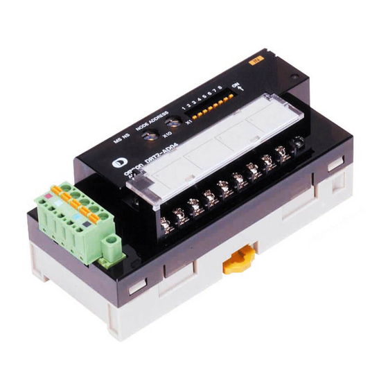
Sign In
Upload
Manuals
Brands
Omron Manuals
Network Hardware
DeviceNet DRT2-AD04
Omron DeviceNet DRT2-AD04 Manuals
Manuals and User Guides for Omron DeviceNet DRT2-AD04. We have
3
Omron DeviceNet DRT2-AD04 manuals available for free PDF download: Operation Manual, Manual
OMRON DeviceNet DRT2-AD04 Operation Manual (596 pages)
DeviceNet Slaves
Brand:
OMRON
| Category:
Network Hardware
| Size: 12.97 MB
Table of Contents
Table of Contents
7
Precautions
14
Intended Audience
15
General Precautions
16
Safety Precautions
17
Operating Environment Precautions
18
Application Precautions
19
Conformance to EC Directives
21
Applicable Directives
21
Concepts
21
Section 1 Smart Slaves and Features
22
Smart Slaves and Features
22
DRT2 Features
23
Overview
23
Features
23
DRT2 Slaves
28
General-Purpose Slaves
28
Environment-Resistive Slaves
30
Analog Slaves
31
Smart Slave Feature Support
32
Installing and Connecting Slaves
38
Section 2 Example System Startup
42
Example System Startup
42
Basic Procedures and Configuration Examples
43
Basic Procedures
43
System Configuration Example
43
Preparations
44
Selecting Units
44
Wiring
44
Communications Power Supply
44
Setting and Wiring Hardware
45
Mounting and Setting the Master Unit
45
Mounting and Setting Slaves
46
Mounting Connecting Devices
47
Connecting Cables
47
Starting Communications
48
Creating I/O Tables for the Master Unit
48
Starting the System
49
Creating and Registering Scan Lists
49
Checking Operation
50
Indicator Status
50
Reading and Writing Data
50
Section 3 Common Slave Specifications
52
Common Slave Specifications
52
Common Slave Specifications
53
Communications Specifications
53
MS and NS Indicators
53
Devicenet Remote I/O Communications
55
Overview of Remote I/O Allocations for Smart Slaves
55
I/O Allocations for Smart Slaves
57
I/O Allocation with the Configurator (Ver. 2.@ or Later)
63
Section 4 Functions of All Slaves, General-Purpose Slaves, and Environment-Resistive Slaves
68
And Environment-Resistive Slaves
68
Maintenance Mode Window and Main Window
69
Normal Window
69
Maintenance Mode Window
70
Device Monitor Window
72
Common Slave Functions
73
Automatic Baud Rate Recognition
73
Network Power Supply Voltage Monitor
74
Unit Conduction Time Monitor
75
Slave Comments
76
I/O Comments
78
Communications Error History Monitor
80
Last Maintenance Date
81
Functions of General-Purpose Slaves and Environment-Resistive Slaves
82
I/O Power Status Monitor
82
Input Filter
83
Power on Delay
85
Contact Operation Counter
85
Total on Time Monitor
87
Operation Time Monitor
89
Sensor Disconnected Detection
93
Detection of Sensor Power Short-Circuit
95
External Load Short-Circuit Detection
97
4-3-10 External Load Disconnected Detection
101
Section 5 General-Purpose Slaves
104
Common Specifications for General-Purpose Slaves
106
Current Consumption and Weights
106
Connecting Communications Cables to General-Purpose Slaves
108
Connecting Communications Cables
108
Connecting Communications Cables to the Nodes
110
Maintenance Information Window
112
Checking Maintenance Information
113
Mounting Terminating Resistors
112
Remote I/O Terminals with Transistors
118
Node Address, Baud Rate, and Output Hold/Clear Settings
118
Increasing I/O Using an Expansion Unit
121
Remote I/O Terminals with 8 Transistor Inputs
123
DRT2-ID08 (NPN) and DRT2-ID08-1 (PNP)
123
Remote I/O Terminals with 8 Transistor Outputs
125
DRT2-OD08 (NPN) and DRT2-OD08-1 (PNP)
126
Remote I/O Terminals with 16 Transistor Inputs
128
DRT2-ID16 (NPN) and DRT2-ID16-1 (PNP)
128
Remote I/O Terminals 16 Transistor Outputs
131
DRT2-OD16 (NPN) and DRT2-OD16-1 (PNP)
131
Remote I/O Terminals with 8 Transistor Inputs and 8 Transistor Outputs: DRT2-MD16 (NPN) and DRT2-MD16-1 (PNP)
134
Remote I/O Terminal with 16 Relay Outputs: DRT2-ROS16
137
Remote I/O Terminal Expansion Units with 8 Transistor Inputs: XWT-ID08 (NPN) and XWT-ID08-1 (PNP)
141
Remote I/O Terminal Expansion Units 16 Transistor Inputs
144
XWT-ID16 (NPN) and XWT-ID16-1 (PNP)
145
5-5-11 Remote I/O Terminal Expansion Units with 8 Transistor Outputs
147
XWT-OD08 (NPN) and XWT-OD08-1 (PNP)
147
5-5-12 Remote I/O Terminal Expansion Units with 16 Transistor Outputs
150
XWT-OD16 (NPN) and XWT-OD16-1 (PNP)
150
Transistor Remote Input Terminals with 16 Points and 3-Tier I/O Terminal Blocks: DRT2-ID16TA (NPN) and DRT2-ID16TA-1 (PNP)
153
Transistor Remote Output Terminals with 16 Points and 3-Tier I/O Terminal Blocks: DRT2-OD16TA (NPN) and DRT2-OD16TA-1 (PNP)
156
5-5-15 Transistor Remote I/O Terminals with 8 Inputs and 8 Outputs and
160
Drt2-Md16Ta-1 (Pnp)
160
5-5-16 Mounting in Control Panels
163
5-5-17 Wiring the I/O Power Supply and I/O Lines
164
Connector Terminals with Transistors
165
Node Address, Baud Rate, and Output Hold/Clear Settings
165
Industry Standard Sensor Connector Assembly, Wiring, and Installation
166
Connector Terminals with 16 Transistor Inputs: DRT2-ID16S (NPN) and DRT2-ID16S-1 (PNP)
169
Connector Terminals
171
Outputs): DRT2-MD16S (NPN) and DRT2-MD16S-1 (PNP)
171
Transistor Remote Input Terminals with 16 Points and Connectors
174
DRT2-ID16ML(X) (NPN) and DRT2-ID16ML(X)-1 (PNP)
174
Connector Terminals (MIL Connector Type with 16 Outputs): DRT2-OD16ML(X) (NPN) and DRT2-OD16ML(X)-1 (PNP)
178
Transistor Remote Input Terminals with 32 Points and Connectors
181
DRT2-ID32ML (NPN) and DRT2-ID32ML-1 (PNP)
181
Transistor Remote Output Terminals with 32 Points and Connectors
187
DRT2-OD32ML (NPN) and DRT2-OD32ML-1 (PNP)
187
Transistor Remote I/O Terminals with 16 Inputs and
191
Drt2-Md32Ml-1 (Pnp)
191
Board-Type Connector Terminals with 32 Inputs and
205
Drt2-Id32Bv (Npn)/Drt2-Id32Bv-1 (Pnp)
205
Board-Type Connector Terminals with 32 Outputs and
209
Drt2-Od32Bv (Npn)/Drt2-Od32Bv-1 (Pnp)
209
Board-Type Connector Terminals with 16 Inputs, 16 Outputs and MIL Connectors: DRT2-MD32B (NPN)/DRT2-MD32B-1 (PNP) and
213
Drt2-Md32Bv (Npn)/Drt2-Md32Bv-1 (Pnp)
213
Screw-Less Clamp Terminals
224
Node Address, Baud Rate, and Output Hold/Clear Settings
224
Wiring to a Screw-Less Clamp Terminal Block
224
I/O Indicators
226
Screw-Less Clamp Terminals with 16 Transistor Inputs
226
Screw-Less Clamp Terminals with 32 Transistor Inputs
230
Screw-Less Clamp Terminals with and 16 Transistor Outputs
235
Screw-Less Clamp Terminals with and 32 Transistor Outputs
241
Screw-Less Clamp Terminals with 16 Transistor Inputs and Outputs
246
Mounting to a Control Panel
252
Section 6 Environment-Resistive Slaves
254
Common Specifications for Environment-Resistive Slaves
255
Current Consumption, Weight, Enclosure Ratings
256
I/O Indicators
256
Connecting Communications Cables to Environment-Resistive Slaves
257
System with Slaves Using Round Connectors Only
257
System with Slaves Using Round Connectors and Regular Square
258
Connectors
258
Communications Cables for Environment-Resistive Terminals
258
Example System Assembly
260
Maintenance Information Window
260
Checking Maintenance Information
260
Advanced Environment-Resistive Terminals
266
Node Address, Baud Rate, and Output Hold/Clear Settings
266
Environment-Resistive Terminals with 8 Transistor Inputs (IP67): DRT2-ID08C (NPN) and DRT2-ID08C-1 (PNP)
266
Environment-Resistive Terminals with 16 Transistor Inputs (IP67): DRT2-HD16C (NPN) and DRT2-HD16C-1 (PNP)
271
Environment-Resistive Terminals with 8 Transistor Outputs (IP67): DRT2-OD08C (NPN) and DRT2-OD08C-1 (PNP)
276
Standard Environment-Resistive Terminals
281
Node Address, Baud Rate, and Output Hold/Clear Settings
281
Environment-Resistive Terminals with 4 Transistor Inputs (IP67): DRT2-ID04CL (NPN) and DRT2-ID04CL-1 (PNP)
282
Environment-Resistive Terminals with 8 Transistor Inputs (IP67): DRT2-ID08CL (NPN) and DRT2-ID08CL-1 (PNP)
286
Environment-Resistive Terminals with 16 Transistor Inputs (IP67): DRT2-HD16CL (NPN) and DRT2-HD16CL-1 (PNP)
289
Environment-Resistive Terminals with 4 Transistor Outputs (IP67): DRT2-OD04CL (NPN) and DRT2-OD04CL-1 (PNP)
293
Environment-Resistive Terminals with 8 Transistor Outputs (IP67): DRT2-OD08CL (NPN) and DRT2-OD08CL-1 (PNP)
296
Environment-Resistive Terminals with 16 Transistor Outputs (IP67): DRT2-WD16CL (NPN) and DRT2-WD16CL-1 (PNP)
299
Environment-Resistive Terminals with 8 Transistor Inputs and 8 Transistor Outputs (IP67): DRT2-MD16CL (NPN) and DRT2-MD16CL-1 (PNP)
303
Mounting and Wiring Environment-Resistive Slaves
307
Mounting in Control Panels
307
Wiring the Internal Power Supply, I/O Power Supply, and I/O Lines
307
Analog Slaves
312
Overview of Analog Slaves
313
Common Procedures
329
Maintenance Information Window
331
Analog Input Terminals
336
Analog Output Terminals
380
Temperature Input Terminals
398
Communications Timing
464
Remote I/O Communications Characteristics
465
Message Communications Characteristics
474
Troubleshooting and Maintenance
476
Indicators and Error Processing
477
Troubleshooting
478
Maintenance
487
A Devicenet Explicit Messages
490
For All Slaves at Once
560
D Connectable Devices
574
E Current Consumption Summary
584
F Precautions with Connecting Two-Wire DC Sensors
588
Index
590
Revision History
596
Advertisement
Omron DeviceNet DRT2-AD04 Operation Manual (282 pages)
DeviceNet Slaves
Brand:
Omron
| Category:
Industrial Electrical
| Size: 6.52 MB
Table of Contents
Precautions
10
Table of Contents
10
Intended Audience
11
General Precautions
12
Safety Precautions
13
Operating Environment Precautions
14
Application Precautions
15
EC Directives
17
Section 1 Smart Slaves and Features
18
DRT2 Features
19
Overview
19
Features
19
DRT2 Slaves
23
General-Purpose Slaves
23
Environment-Resistive Slaves
23
Analog Slaves
23
Smart Slave Feature Support
24
Installing and Connecting Slaves
25
Section 2 Example System Startup
28
Basic Procedures and Configuration Examples
29
Basic Procedures
29
System Configuration Example
29
Preparations
30
Selecting Units
30
Wiring
30
Communications Power Supply
30
Setting and Wiring Hardware
31
Mounting and Setting the Master Unit
31
Mounting and Setting Slaves
32
Mounting Connecting Devices
33
Connecting Cables
33
Starting Communications
34
Creating I/O Tables for the Master Unit
34
Starting the System
34
Creating and Registering Scan Lists
35
Checking Operation
36
Indicator Status
36
Reading and Writing Data
36
Section 3 Common Slave Specifications
38
Common Slave Specifications
39
Communications Specifications
39
MS and NS Indicators
39
Devicenet Remote I/O Communications
41
Overview of Remote I/O Allocations for Smart Slaves
41
I/O Allocations for Smart Slaves
43
I/O Allocation with the Configurator (Ver. 2.@ or Later)
47
Section 4 Functions
54
Maintenance Mode Window and Main Window
55
Maintenance Mode Window
55
Common Slave Functions
56
Automatic Baud Rate Recognition
56
Network Power Supply Voltage Monitor
57
Unit Conduction Time Monitor
58
Slave Comments
59
I/O Comments
61
Communications Error History Monitor
63
Last Maintenance Date
64
Remote I/O Terminal and Environment-Resistive Terminal Functions
65
I/O Power Status Monitor
65
Input Filter
66
Power on Delay
68
Contact Operation Counter
68
Total on Time Monitor
70
Operation Time Monitor (Remote I/O Terminals Only)
72
Sensor Disconnected Detection (Environment-Resistive Terminal Input Units Only)
75
Detection of Sensor Power Short-Circuit (Environment-Resistive Terminal Input Units Only)
76
External Load Short-Circuit Detection (Environment-Resistive Terminal Output Units Only)
78
Section 5 General-Purpose Slaves
82
Common Specifications for General-Purpose Slaves
83
Current Consumption and Weights
83
Connecting Communications Cables to General-Purpose Slaves
84
Connecting Communications Cables
84
Connecting Communications Cables to the Nodes
86
Mounting Terminating Resistors
87
Remote I/O Terminals with Transistors
88
Node Address, Baud Rate, and Output Hold/Clear Settings
88
Increasing I/O Using an Expansion Unit
90
Remote I/O Terminals with Transistors and 16 Inputs: DRT2-ID16 (NPN) and DRT2-ID16-1 (PNP)
92
Remote I/O Terminals with Transistors and 16 Outputs: DRT2-OD16 (NPN) and DRT2-OD16-1 (PNP)
94
XWT-ID08 (NPN) and XWT-ID08-1 (PNP)
97
XWT-ID16 (NPN) and XWT-ID16-1 (PNP)
100
Remote I/O Terminal Expansion Units with Transistors and 8 Outputs:
103
Remote I/O Terminal Expansion Units with Transistors and 16 Outputs:
105
Mounting in Control Panels
108
5-3-10 Wiring the I/O Power Supply and I/O Lines
108
Section 6 Environment-Resistive Slaves
110
Common Specifications for Environment-Resistive Slaves
111
Current Consumption, Weight, Enclosure Ratings
111
I/O Indicators
111
Connecting Communications Cables to Environment-Resistive Slaves
112
System with Slaves Using Round Connectors Only
112
System with Slaves Using Round Connectors and Regular Square Connectors
113
Communications Cables for Environment-Resistive Terminals
113
Example System Assembly
115
Environment-Resistive Terminals
116
Node Address, Baud Rate, and Output Hold/Clear Settings
116
Environment-Resistive Terminals with 8 Transistor Inputs (IP67): DRT2-ID08C (NPN) and DRT2-ID08C-1 (PNP)
116
Environment-Resistive Terminals with 16 Transistor Inputs (IP67): DRT2-HD16C (NPN) and DRT2-HD16C-1 (PNP)
121
Environment-Resistive Terminals with 8 Transistor Outputs (IP67): DRT2-OD08C (NPN) and DRT2-OD08C-1 (PNP)
126
Mounting in Control Panels
131
Wiring the Internal Power Supply, I/O Power Supply, and I/O Lines
132
Section 7 Analog Slaves
136
Overview of Analog Slaves
137
DRT2 Analog Slaves
137
Comparison of DRT1 and DRT2 Functions
137
List of Data Processing Functions
139
Analog Data Operation Flowcharts (Analog Input Terminals)
140
Selecting Analog Data (Analog Input Terminals)
140
I/O Data Allocated in the Master
141
Allocating I/O Data in the Master
143
Procedure for Allocating I/O in the Master
145
Application Procedure Flowchart
146
Common Procedures
147
Connecting Communications Cables
147
Node Address and Baud Rate Settings
147
Mounting in Control Panels
148
Wiring the I/O Lines
149
Analog Input Terminals
149
DRT2-AD04 Analog Input Terminals
149
I/O Data Allocation Methods
155
Functions and Settings
165
Calculating the Conversion Cycle
187
Analog Output Terminals
188
DRT2-DA02 Analog Output Terminal
188
I/O Data Types and Allocation Methods
193
Functions and Setting Methods
198
Section 8 Communications Timing
208
Remote I/O Communications Characteristics
209
I/O Response Time
209
Communications Cycle Time and Refresh Time
214
More than One Master in Network
216
System Startup Time
217
Message Communications Characteristics
218
Message Communications Time
218
Section 9 Troubleshooting and Maintenance
220
Indicators and Error Processing
221
Error Occurring in the Slave Unit
221
Troubleshooting
222
Slave Unit Troubleshooting
222
Maintenance
224
Cleaning
224
Inspection
225
Replacing Units
225
Omron DeviceNet DRT2-AD04 Manual (31 pages)
Brand:
Omron
| Category:
Touch terminals
| Size: 2.1 MB
Table of Contents
Table of Contents
5
Matters to be Accepted
6
Object Product
6
Comparing DRT2-AD04/DA02 and R7D-SV4/YV2/YS2 Specifications
7
Analog Input Terminal
7
Analog Output Terminals
9
External Dimensions
10
Switch Setting Method
11
DRT2-AD04 and R7D-SV4
11
DRT2-DA02 and R7D-YV2
13
DRT2-DA02 and R7D-YS2
14
Wiring Method
15
DRT2-AD04 and R7D-SV4
15
DRT2-DA02 and R7D-YS2
16
DRT2-DA02 and R7D-YV2
17
Setting by PC Configurator Software
18
Replacing the Unit
21
Replacement of Unit at Fixed Assignment
21
Replacement of Unit at Free Assignment
23
Terminology and Definitions
28
Reference Information
29
Notes
30
Revision History
30
Advertisement
Advertisement
Related Products
Omron DeviceNet DRT2-OD16TA
Omron DeviceNet DRT2-OD32ML-1
Omron DeviceNet DRT2-OD16SLH
Omron DeviceNet DRT2-OD32SL
Omron DeviceNet DRT2-OD32SLH
Omron DeviceNet DRT2-ID04CL
Omron DeviceNet DRT2-MD32BV-1
Omron DeviceNet DRT2-OD16SL-1
Omron DeviceNet DRT2-MD32BV
Omron DeviceNet DRT2-OD32B-1
Omron Categories
Blood Pressure Monitor
Controller
Accessories
Switch
Inverter
More Omron Manuals
Login
Sign In
OR
Sign in with Facebook
Sign in with Google
Upload manual
Upload from disk
Upload from URL