
Related Manuals for Omron DRT2-AD04


Summary of Contents for Omron DRT2-AD04
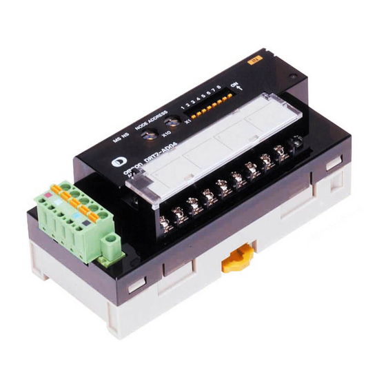
- Page 1 DeviceNet Analog I/O Terminals Replace Guide From DRT2-AD/DA to R7 Series OMRON DRT2-AD04 DRT2-DA02 M-SYSTEM CO., LTD. Remote I/O R7 Series R7D-SV4 R7D-YV2 R7D-YS2 P155-E1-01...
- Page 2 ■Introduction This document is intended for experienced users who have designed remote I/O communication systems using DeviceNet, This is the summary of points to smoothly transfer the system to R7D-SV4/R7D-YV2/YS2 manufactured by M- SYSTEM CO., LTD. This document is a summary of only the points. For detailed operating procedures, refer to the documentation and technical documentation in "7.
- Page 3 (a) Exclusive Warranty. Omron’s exclusive warranty is that the Products will be free from defects in materials and workmanship for a period of twelve months from the date of sale by Omron (or such other period expressed in writing by Omron). Omron disclaims all other warranties, express or implied.
- Page 4 Performance Data Data presented in Omron Company websites, catalogs and other materials is provided as a guide for the user in determining suitability and does not constitute a warranty. It may represent the result of Omron’s test conditions, and the user must correlate it to actual application requirements. Actual performance is subject to the Omron’s Warranty and Limitations of Liability...
-
Page 5: Table Of Contents
Table of Contents Matters to be Accepted ................エラー! ブックマークが定義されていません。 Intended Audience ................................. 6 Object product ..................................6 Comparing DRT2-AD04/DA02 and R7D-SV4/YV2/YS2 specifications ................. 7 1.1 Analog input terminal ..............................7 1.2 Analog Output Terminals ..............................9 1.3 EXTERNAL DIMENSIONS ............................10 Switch setting method .............................. -
Page 6: Matters To Be Accepted
・ A customer who has previously been designed a remote I/O communication system using DeviceNet and will be responsible for replacing the unit from DRT2-AD04/DA02 to R7D-SV4/YV2/YS2 in the future. ・ Omron or your retailer's sales representative or SE that supports the introduction of the above customer. Object product... -
Page 7: Comparing Drt2-Ad04/Da02 And R7D-Sv4/Yv2/Ys2 Specifications
Comparing DRT2-AD04/DA02 and R7D-SV4/YV2/YS2 specifications This chapter compares the functions and specific cations of DRT2-AD04/DA02 and R7D-SV4/YV2/YS2. 1.1 Analog input terminal Item DRT2-AD04 R7D-SV4 Number of analog 4 points input points Input range Voltage Current Voltage Current 0 ~ 5V 0 ~... - Page 8 Conversion rate calculation function Comparator function User calibration function Integral function Last maintenance day function...
-
Page 9: Analog Output Terminals
1.2 Analog Output Terminals Item DRT2-DA02 R7D-YV2 R7D-YS2 Number of analog 2 points output points Output range Voltage Current Voltage Current 0 ~ 5V 0 ~ 20mA 0~5V 4~20mA 1 ~5V 4~ 20mA 1~5V 0 ~ 10V -5V~+5V - 10 ~ +10V 0~10V -10V~+10V -1~+1V... -
Page 10: External Dimensions
1.3 EXTERNAL DIMENSIONS R7D-SV4 R7D-YV2/YS2... -
Page 11: Switch Setting Method
Switch setting method DRT2-AD04/DA02 and R7D-SV4/YV2/YS2 settings are described with both units. I will explain it. Safety Key Points Be sure to turn off the power to the slave before making sets. 2.1 DRT2-AD04 and R7D-SV4 DRT2-AD04 R7D-SV4 Set the node address and input range. - Page 12 Setting input range Setting input range Conversion Speed/Accuracy Setting Conversion Speed/Accuracy Setting There is no setting.
-
Page 13: Drt2-Da02 And R7D-Yv2
2.2 DRT2-DA02 and R7D-YV2 DRT2-DA02 R7D-YV2 Set the node address and output range Set the node address, communication speed, output at communication interruption, and output range. ・Model DRT2-DA02 ・Model R7D-YV2 Setting the Node Address Setting the Node Address Setting the Baud Rate Setting the Baud Rate There is no setting. -
Page 14: Drt2-Da02 And R7D-Ys2
2.3 DRT2-DA02 and R7D-YS2 DRT2-DA02 R7D-YS2 Set the node address and output range. Set the node address, communication speed, output at communication interruption, and output range. ・Model DRT2-DA02 ・Model R7D-YS2 Setting the Node Address Setting the Node Address Setting the Baud Rate Setting the Baud Rate There is no setting. -
Page 15: Wiring Method
Wiring method 3.1 DRT2-AD04 and R7D-SV4 DRT2-AD04 R7D-SV4 Wire each input unit according to the voltage input Wire each input unit according to the voltage input or or current input as shown below. current input as shown below. Terminal connection diagram... -
Page 16: Drt2-Da02 And R7D-Ys2
3.2 DRT2-DA02 and R7D-YS2 DRT2-DA02 R7D-YS2 Wire each output unit according to the voltage output or current output as shown below. -
Page 17: Drt2-Da02 And R7D-Yv2
3.3 DRT2-DA02 and R7D-YV2 DRT2-DA02 R7D-YV2 Wire each output unit according to the voltage output or current output as shown below. -
Page 18: Setting By Pc Configurator Software
Setting by PC Configurator Software For the R7D series manufactured by M-System, the range of each channel can be set by using the PC Configurator software. The following sections describe how to set the range for each channel. R7CON Operating Environment ・WindowsXP, Windows7 (32-bit/64-bit) or Windows10 (32-bit/64-bit) installed correctly A DOS/V compatible personal computer. - Page 19 4 Select the COM port by clicking the "Setting" button. The COM port selection screen appears. Select the COM port you want to use, Click the OK button. 5 After connecting, the initial screen is displayed. 6 Click Setting2. 7 This displays the range selection screen.
- Page 20 9 Change the required CH range. 10 Download the configuration...
-
Page 21: Replacing The Unit
■When DIP switch 8 is ON, it is not necessary to check the settings using the DIP switch. Sets R7D- If DRT2-AD04/DA02 range is set to the DIP switch and all channels are SV4/YV2 range. set to the same range, use the DIP switch to set R7D-SV4/YV2 range. - Page 22 Setting the Baud Rate Set the rotary switch to 3 to 9: Automatic follow-up. Connect the unit. After changing the wiring to the terminal of R7D-SV4/YV2/YS2, connect DeviceNet circuit to the communication connector of DevicNet. Turn on the power. Check that MS and NS of R7D-SV4/YV2/YS2 are lit in green.
-
Page 23: Replacement Of Unit At Free Assignment
5.2 Replacement of Unit at Free Assignment The following procedure shows how to replace DRT2-AD04 allocated in 4ch from 3310Ch with a R7D-SV4. For details on how to obtain EDS files for the R7D series and how to install EDS files on CX-Integrator, refer to SBCZ- 607B of the CJ Series DeviceNet Connectivity Guide (R7 Series) E M-System Remote I/O. - Page 24 ■When DIP switch 8 is ON, it is not necessary to check the settings using the DIP switch. Sets R7D-SV4 If DRT2-AD04 range is set to the DIP switch and all channels are set to range. the same range, use the DIP switch to set R7D-SV4/YV2 range.
- Page 25 Removes a DRT2- AD04 from the scan list. Select R7D-SV4 EDS-file. Register with node address "1".
- Page 26 Select the master I/O assignment (IN) from the device parameter edit of the master. To R7D-SV4 allocation channel Changed to 3310 Write the scan list to the master.
- Page 27 Connect the unit. After changing the wiring to the terminal of R7D-SV4/YV2/YS2, connect DeviceNet circuit to the communication connector of DevicNet. Turn on the power. Check that MS and NS of R7D-SV4/YV2/YS2 are lit in green.
-
Page 28: Terminology And Definitions
Terminology and definitions Term Explanation and define Remote I/O This is communication that always shares data between CPU module Communication and slaves. Communication starts automatically by turning on the power supply (communication power supply to the slave and power supply of PLC main unit) and data sharing starts between I/O memory area of CPU unit and the slave unit. -
Page 29: Reference Information
Man.No. Type Manual name OMRON W380 Model CJ1W-DRM21 DeviceNet Units Operation Manual Model CS1W-DRM21 (-V1) OMRON W404 Model DRT2-AD04 DRT2 Series DeviceNet Slave Operation Manual Model DRT2-DA02 Model WS02-CXPC □-V8 OMRON W446 SYSMAC CX-Programmer Operation Manual OMRON W464 Model CXONE-AL□□C- SYSMAC CX-Integrator Operation Manual V3/AL□□D-V3... -
Page 30: Notes
Notes (1) When constructing a system based on this document, please read the instruction manual of the product to be constructed and confirm the specs, performance and safety. The symbols used in this document have the following meanings: Safety Key Points Indicates what should be done or avoided in order to use the product safely. - Page 31 Note: Do not use this document to operate the Unit. 2021 P155-E1-01 1221 (1221)
Need help?
Do you have a question about the DRT2-AD04 and is the answer not in the manual?
Questions and answers