Sign In
Upload
Manuals
Brands
Motorola Manuals
Two-Way Radio
APX4000 XH
Motorola APX4000 XH Manuals
Manuals and User Guides for Motorola APX4000 XH. We have
4
Motorola APX4000 XH manuals available for free PDF download: Detailed Service Manual, User Manual
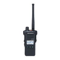
Motorola APX4000 XH Detailed Service Manual (1096 pages)
Brand:
Motorola
| Category:
Two-Way Radio
| Size: 57.49 MB
Table of Contents
Table of Contents
11
Computer Software Copyrights
2
Disclaimer
2
Document Copyrights
2
Foreword
2
Manual Revisions
2
Product Safety and Rf Exposure Compliance
2
Trademarks
2
Document History
5
Commercial Warranty
7
Table of Contents
11
List of Tables
14
List of Figures
16
Chapter 1 Introduction
23
General
23
Notations Used in this Manual
24
Chapter 2 Radio Power
25
General
25
Table 2-1. IMPRES Batteries
25
DC Power Routing
26
Figure 2-1. DC Power Distribution
26
Chapter 3 Theory of Operation
27
Figure 3-1. APX 2000/ APX 4000/ APX 4000Li Overall Block Diagram
28
Figure 3-2. APX 1000 (900 Mhz) Overall Block Diagram
29
Main Board
30
Figure 3-3. Transceiver (VHF) Block Diagram (Power and Control Omitted)
30
Figure 3-4. Transceiver (UHF1/UHF2) Block Diagram (Power and Control Omitted)
31
Figure 3-5. Transceiver (700/800 Mhz) Block Diagram (Power and Control Omitted)
32
Table 3-1. Battery Connector J3
33
Figure 3-6. Transceiver (900 Mhz) Block Diagram (Power and Control Omitted)
33
Figure 3-7. Receiver Block Diagram (VHF)
34
Figure 3-8. Receiver Block Diagram (UHF1/UHF2)
35
Figure 3-9. Receiver Block Diagram (700/800 Mhz )
35
Figure 3-10. Receiver Block Diagram (900 Mhz )
35
Figure 3-11. Transmitter Block Diagram (VHF/UHF1/UHF2/900 Mhz)
37
Figure 3-12. Transmitter Block Diagram (700/800 Mhz)
38
Figure 3-13. Synthesizer Block Diagram (VHF)
42
Figure 3-14. Synthesizer Block Diagram (UHF1/UHF2)
43
Figure 3-15. Synthesizer Block Diagram (700/800 Mhz)
43
Figure 3-16. Synthesizer Block Diagram (900 Mhz)
44
Controller
49
Figure 3-17. Controller Interconnection Diagram
49
Figure 3-18. Controller Electrical Overview
51
Figure 3-19. Controller DC Block Diagram
52
Table 3-2. DC Supplies and Sources for Controller
53
Table 3-3. Mako's LDO and Supplies
54
Figure 3-20. V_SW_1.4 Switched Power Supply
55
Table 3-4. Pulse Switching Combination
56
Figure 3-21. 5V Switched Power Supply
56
Figure 3-22. Power-Up Timing Regulators
57
Figure 3-23. Controller Clock Architecture
58
Table 3-5. Controller Clock Distribution
59
Figure 3-24. Overview of OMAP Interconnection with Controller Peripherals
60
Figure 3-25. OMAP Memory Interface
61
Figure 3-26. RX/ TX SSI Configuration
62
Figure 3-27. Audio SSI Configuration
63
Figure 3-28. SPI and I2C Configuration
64
Figure 3-29. CPLD Block Diagram
65
Figure 3-30. Audio TX Path Block Diagram
66
Figure 3-31. RX Audio Path Block Diagram
67
Figure 3-32. Control Top Block Diagram (APX 2000/ APX 4000/ APX 4000Li/ APX 1000 (900 Mhz))
68
Figure 3-33. Control Top Block Diagram (APX 2000/ APX 4000 (Two Knobs))
69
Figure 3-34. Display Circuit Detail Overview Block Diagram
70
Table 3-6. Color Schemes
71
Figure 3-35. Lighting Controller Overview
72
Table 3-7. Key Map Matrix
73
Figure 3-36. Keypad Interface Outline
73
Figure 3-37. GCAI Signal Configuration
74
Table 3-8. P1 Pin Assignment
75
Figure 3-38. GCAI Connector
75
Table 3-9. GCAI Connector Pin Assignment
76
Figure 3-39. APX 2000/ APX 4000 Encryption Architecture
77
Table 3-10. Secure Keypad KIT Numbers
78
Global Positioning Sytem (GPS)
79
Table 3-11. Power and I/O Pins for NL5500
80
Figure 3-40. GPS Block Diagram
80
Accelerometer
81
Table 3-12. SPI Interface
81
Figure 3-41. Accelerometer Block Diagram
81
Table 3-13. Register Address Map
82
Bluetooth
83
Figure 3-42. Relation of Bluetooth & LF Antenna Assembly to Main & Keypad Boards
83
Figure 3-43. Bluetooth Connection Flowchart
84
Figure 3-44. Bluetooth/Controller Interface with Clock Sources
85
Figure 3-45. Bluetooth Functional Block Diagram
85
Figure 3-46. Bluetooth Low-Frequency Circuit Block Diagram
86
Figure 3-47. Bluetooth Low-Frequency Pairing Data Path
86
Figure 3-48. Detailed Low-Frequency Transmit/Receive Paths
87
Figure 3-49. Chip Power-Up/Power-Down Sequence (Exernal Input/Output Shown)
87
Figure 3-50. Current Distribution Tree for Bluetooth Circuitry
88
Table 3-14. Bluetooth Host Processor UART I/O
89
Table 3-15. SPI I/O
90
Figure 3-51. Bluetooth LF UART Connection Block Diagram
90
Table 3-16. USB I/O
91
Figure 3-52. Bluetooth USB Interface to Main Board
91
Table 3-17. GPIO I/O
92
Chapter 4 Troubleshooting Procedures
93
Handling Precautions
93
Recommended Service Tools
94
Table 4-1. Recommended Service Tools
94
Standard Bias Table
95
Table 4-2. Standard Operating Bias - DC Voltages
95
Table 4-3. Standard Operating Bias - Clock Sources
95
Power-Up Self-Check Errors
96
Table 4-4. Power-Up Self-Check Error Codes
96
Power-Up Self-Check Diagnostics and Repair (Not for Field Use)
97
Table 4-5. Power-Up Self-Check Diagnostic Actions
97
Chapter 5 Troubleshooting Charts
99
List of Troubleshooting Charts
99
Table 5-1. Troubleshooting Charts
99
Main Troubleshooting Flowchart
101
Power-Up Failure
102
DC Supply Failure
113
Main Display Failure
120
Volume/Channel Error
121
Volume Set Error (APX 2000/ APX 4000 (Two Knobs))
122
Channel Select Error (APX 2000/ APX 4000 (Two Knobs))
123
Keypad Error
124
5.10 Side Button Error
125
5.11 RX Audio Error
126
5.12 TX Audio Error
128
5.13 Keyload/Secure Hardware/Memory
130
RX RF Failure
132
5.15 FGU Failure
143
VCO Failure
144
5.17 GPS Failure
150
Bluetooth Failure
152
PA Failure
157
Chapter 6 Troubleshooting Waveforms
163
List of Waveforms
163
Table 6-1. List of Waveforms
163
Clocks
164
Figure 6-1. 32 Khz Clock Waveform
164
Figure 6-2. 4 Mhz Clock Waveform
165
Figure 6-3. 12 Mhz Clock Waveform
166
Figure 6-4. 16.8 Mhz Clock Waveform
167
Figure 6-5. 24 Mhz Clock Waveform
168
Audio SSI
169
Figure 6-6. Audio SSI - Red Tx Waveform
169
Figure 6-7. Audio SSI - Red Rx Waveform
170
Figure 6-8. Audio SSI - Sync. Waveform
171
Figure 6-9. Audio SSI - BCLK. Waveform
172
Rx Ssi
173
Figure 6-10. RX SSI - CLK. Waveform
173
Figure 6-11. RX SSI - da Waveform
174
Figure 6-12. RX SSI - Fsync. Waveform
175
Tx Ssi
176
Figure 6-13. TX SSI - TX CLK. Waveform
176
Figure 6-14. TX SSI - da Waveform
177
Figure 6-15. TX SSI - Fsync. Waveform
178
Spi
179
Figure 6-16. SPI - CLK Waveform
179
Figure 6-17. CS Waveform
180
I2C Bus
181
Figure 6-18. I2C Bus - SCA Waveform
181
Figure 6-19. I2C Bus - SCA 5V Waveform
182
Figure 6-20. I2C Bus - SDA Waveform
183
One Wire
184
Figure 6-21. 1-Wire Waveform
184
Gcai
185
Figure 6-22. GCAI - GPIO0 Waveform
185
Figure 6-23. GCAI - GPIO4 Waveform
186
6.10 Usb
187
Figure 6-24. USB - D- Waveform
187
Figure 6-25. USB - D+ Waveform
188
6.11 Sdram
189
Figure 6-26. SDRAM - CLK Waveform
189
Figure 6-27. SDRAM - CLKX Waveform
190
6.12 Flash Control
191
Figure 6-28. FLASH CONTROL - ADV Waveform
191
Figure 6-29. FLASH CONTROL - CS3 Waveform
192
Figure 6-30. FLASH CONTROL - OE Waveform
193
Figure 6-31. FLASH CONTROL - RDY Waveform
194
Figure 6-32. FLASH CONTROL - WE Waveform
195
6.13 Receive Baseband Signals
196
Figure 6-33. Received Baseband Waveforms
196
6.14 Gps
197
Figure 6-34. GPS TCXO Waveforms
197
Figure 6-35. GPS RTC Waveforms
198
Figure 6-36. GPS UART DATA Waveforms
199
6.15 Bluetooth Troubleshooting Waveforms
200
Table 6-2. Bluetooth Command to TX
200
Table 6-3. Bluetooth Command to RX
201
Table 6-4. Low Frequency Command to TX
201
Table 6-5. Low Frequency Command to RX
201
Table 6-6. Bluetooth Test Points
202
Figure 6-37. Startup Waveforms - Vmax of TP16
203
Figure 6-38. Startup - Timing Difference of TP9 to TP16
204
Figure 6-39. Startup - Timing Difference of TP5 to TP16 and Voltage Statistics
205
Figure 6-40. Startup - Timing Difference of TP4 to TP16 and Time Statistics
206
Figure 6-41. Startup - Timing Difference of TP4 to TP5 and Time Statistics
207
Figure 6-42. Startup - Vmax of TP5 and Time Statistics
208
Figure 6-43. Startup - Vmax of TP4 and Time Statistics
209
Figure 6-44. Startup - Vmax of TP5 and Voltage Statistics
210
Figure 6-45. Startup - Vmax of TP9 and Voltage Statistics
211
Figure 6-46. Startup - Vmax of TP10 and Time Statistics
212
Figure 6-47. Startup - Vmax of TP16 and Voltage Statistics
213
Figure 6-48. Startup - Vmax of TP13 and Voltage Statistics
214
Figure 6-49. Startup - Vmax of TP11 and Voltage Statistics
215
Figure 6-50. Startup - Timing Difference of TP13 to TP16 and Time Statistics
216
Figure 6-51. Startup - Timing Difference of TP10 to TP13 and Time Statistics
217
Figure 6-52. Startup - Timing Difference of TP11 to TP13 and Time Statistics
218
Figure 6-53. Bluetooth CW on Spectrum Analyzer
219
6.16 Bluetooth Steady-State
220
Figure 6-54. Keypad Board - USB D+ Vmax and Packet Timing with Statistics
220
Figure 6-55. Keypad Board - USB D- Vmax and Packet Timing with Statistics
221
Figure 6-56. Keypad Board - VSW_3.6 Voltage Statistics
222
Figure 6-57. Keypad Board - 32 Khz Clock Vmax with Statistics
223
Figure 6-58. Keypad Board Waveforms - LF Coil When TX and RX
224
6.17 LF CW on Spectrum Analyzer
225
Figure 6-59. LF CW on Spectrum Analyzer
225
Chapter 7 Troubleshooting Tables
227
List of Board and IC Signals
227
Table 7-2. Mainboard to Back Kit Flex Connector Interface Pin-Out
228
Table 7-3. Main Back Kit Flex Connector to Main Board Connector Interface Pin-Out
231
Table 7-4. Main Back Kit Flex Connector to Keypad Board Connector Interface Pin-Out
234
Table 7-5. Keypad Board Connector to Mainboard Interface Pin-Out
237
Table 7-6. Keypad Board Connector to Front Kit Flex Interface Pin-Out
240
Table 7-7. Front Kit Connector Interface Pin-Out
242
Table 7-8. GCAI Flex Connector Interface Pin-Out
247
Table 7-9. PTT Flex Connector Interface Pin-Out
249
Table 7-10. Mainboard to Back Kit Flex Connector Interface Pin-Out
250
Table 7-11. Main Back Kit Flex Connector to Main Board Connector Interface Pin-Out
252
Table 7-12. Main Back Kit Flex Connector to Keypad Board Connector Interface Pin-Out
255
Table 7-13. Keypad Board Connector to Mainboard Interface Pin-Out
258
Table 7-14. Keypad Board Connector to Front Kit Flex Interface Pin-Out
261
Table 7-15. Front Kit Connector Interface Pin-Out
264
Table 7-16. GCAI Flex Connector Interface Pin-Out
269
Table 7-17. PTT Flex Connector Interface Pin-Out
271
Table 7-18. Overall GPIO Pin Functions
272
Table 7-19. Primary IC Reference Designator
280
Chapter 8 Schematics, Boards Overlays, and Parts Lists
281
List of Transceiver Schematics and Board Overlays
281
Table 8-1. List of Transceiver Schematics and Board Overlays
281
Figure 8-1. Transceiver (RF) Mainboard Overall Schematic (84012320001)
281
Figure 8-36. Transceiver (RF) Board Layout - Top Side (84012320001)
281
Figure 8-37. Transceiver (RF) Board Layout - Bottom Side (84012320001)
281
Figure 8-40. Transceiver (RF) Mainboard Overall Schematic (84012313002)
281
Figure 8-75. Transceiver (RF) Board Layout - Top Side (84012313002)
282
Figure 8-76. Transceiver (RF) Board Layout - Bottom Side (84012313002)
282
Figure 8-79. Transceiver (RF) Mainboard Overall Schematic (84012432001)
282
Figure 8-114.Transceiver (RF) Board Layout - Top Side (84012432001)
282
Figure 8-115.Transceiver (RF) Board Layout - Bottom Side (84012432001)
282
Figure 8-118.Transceiver (RF) Board Overall Schematic (84012266001)
282
Figure 8-152.Transceiver (RF) Board Layout - Top Side (84012266001)
282
Figure 8-153.Transceiver (RF) Board Layout - Bottom Side (84012266001)
282
Transceiver (RF) Boards: VHF (84012320001 / PC000352A01)
285
Figure 8-4. Controller Mainboard Circuit
288
Figure 8-5. ANTSWI Circuit
289
Figure 8-6. TX HF Circuit
290
Figure 8-7. Power Amplifier (PA) Circuit
291
Figure 8-8. Automatic Level Control Circuit
292
Figure 8-9. Receiver Front End Circuit
293
Figure 8-12. Receiver VCO Circuit
296
Figure 8-13. Transmitter VCO Circuit
297
Figure 8-14. DC Circuit
298
Figure 8-15. RF Interconnects Circuit
299
Figure 8-16. CPLD Circuit
300
Figure 8-17. OMAP User Interface Circuit
301
Figure 8-18. Memory Interface Circuit (84012320001)
302
Figure 8-19. Memory Interface Circuit (PC000352A01)
303
Figure 8-20. Audio Circuit (84012320001)
304
Figure 8-21. Audio Circuit (PC000352A01)
305
Figure 8-22. MAKO/DC Distribution Circuit (84012320001)
306
Figure 8-23. MAKO/DC Distribution Circuit (PC000352A01)
307
Figure 8-24. Serial Interface Circuit
308
Figure 8-25. GPS Bluetooth Circuit
309
Figure 8-26. Controller Circuit (84012320001)
310
Figure 8-27. Controller Circuit (PC000352A01)
311
Figure 8-28. Display/Keypad Lighting Control Circuit (84012320001)
312
Figure 8-29. Display/Keypad Lighting Control Circuit (PC000352A01)
313
Figure 8-30. LCD and Keypad Connector Circuit (84012320001)
314
Figure 8-31. LCD and Keypad Connector Circuit (PC000352A01)
315
Figure 8-32. GCAI MACE BT Interconnect Circuit (84012320001)
316
Figure 8-33. GCAI MACE BT Interconnect Circuit (PC000352A01)
317
Figure 8-38. Transceiver (RF) Board Layout - Top Side (PC000352A01)
322
Figure 8-39. Transceiver (RF) Board Layout - Bottom Side (PC000352A01)
323
Transceiver (RF) Boards: UHF1 (84012313002 / PC000353A01)
363
Figure 8-43. Controller Mainboard Circuit
366
Figure 8-44. DC Circuit
367
Figure 8-45. Receiver Back End Circuit
368
Figure 8-46. Receiver Front End Circuit
369
Figure 8-47. ANTSWI Circuit
370
Figure 8-48. Automatic Level Control Circuit
371
Figure 8-49. Receiver Back End Circuit
372
Figure 8-52. Power Amplifiercircuit
375
Figure 8-53. Transmitter HF Circuit
376
Figure 8-54. Receiver VCO Circuit
377
Figure 8-55. Transmitter VCO Circuit
378
Figure 8-56. CPLD Circuit
379
Figure 8-57. OMAP User Interface Circuit
380
Figure 8-58. Memory Interface Circuit (84012313002)
381
Figure 8-59. Memory Interface Circuit (PC000353A01)
382
Figure 8-60. Audio Circuit (84012313002)
383
Figure 8-61. Audio Circuit (PC000353A01)
384
Figure 8-62. MAKO/DC Distribution Circuit (84012313002)
385
Figure 8-63. MAKO/DC Distribution Circuit (PC000353A01)
386
Figure 8-64. Serial Interface Circuit
387
Figure 8-65. RF Interconnects Circuit
388
Figure 8-66. Controller Circuit (84012313002)
389
Figure 8-67. Controller Circuit (PC000353A01)
390
Figure 8-68. Display/Keypad Lighting Control Circuit (84012313002)
391
Figure 8-69. Display/Keypad Lighting Control Circuit (PC000353A01)
392
Figure 8-70. LCD and Keypad Connector Circuit (84012313002)
393
Figure 8-71. LCD and Keypad Connector Circuit (PC000353A01)
394
Figure 8-72. GCAI MACE BT Interconnect Circuit (84012313002)
395
Figure 8-73. GCAI MACE BT Interconnect Circuit (PC000353A01)
396
Figure 8-74. GPS Bluetooth Circuit
397
Figure 8-77. Transceiver (RF) Board Layout - Top Side (PC000353A01)
400
Figure 8-78. Transceiver (RF) Board Layout - Bottom Side (PC000353A01)
401
Transceiver (RF) Boards: UHF2 (84012432001 / PC000354A01)
441
Figure 8-82. Controller Mainboard Circuit
444
Figure 8-83. DC Circuit
445
Figure 8-84. Transmitter HF Circuit
446
Figure 8-85. Power Amplifier Circuit
447
Figure 8-86. Automatic Level Control Circuit
448
Figure 8-87. Receiver Front End Circuit
449
Figure 8-90. Receiver VCO Circuit
452
Figure 8-91. Transmitter VCO Circuit
453
Figure 8-94. DC Circuit
456
Figure 8-95. RF Interconnects Circuit
457
Figure 8-96. CPLD Circuit
458
Figure 8-97. OMAP User Interface Circuit
459
Figure 8-98. Memory Interface Circuit (84012432001)
460
Figure 8-99. Memory Interface Circuit (PC000354A01)
461
Figure 8-100.Audio Circuit (84012432001)
462
Figure 8-101.Audio Circuit (PC000354A01)
463
Figure 8-102.MAKO/DC Distribution Circuit (84012432001)
464
Figure 8-103.MAKO/DC Distribution Circuit (PC000354A01)
465
Figure 8-104.Serial Interface Circuit
466
Figure 8-105.GPS Bluetooth Circuit
467
Figure 8-106.Controller Circuit (84012432001)
468
Figure 8-107.Controller Circuit (PC000354A01)
469
Figure 8-108.Display/Keypad Lighting Control Circuit (84012432001)
470
Figure 8-109.Display/Keypad Lighting Control Circuit (PC000354A01)
471
Figure 8-110.LCD and Keypad Connector Circuit (84012432001)
472
Figure 8-111.LCD and Keypad Connector Circuit (PC000354A01)
473
Figure 8-112.GCAI MACE BT Interconnect Circuit (84012432001)
474
Figure 8-113.GCAI MACE BT Interconnect Circuit (PC000354A01)
475
Figure 8-116.Transceiver (RF) Board Layout - Top Side (PC000354A01)
478
Figure 8-117.Transceiver (RF) Board Layout - Bottom Side (PC000354A01)
479
Transceiver (RF) Boards: 700 - 800 Mhz (84012266001 / PC000351A01)
519
Figure 8-121.Controller Mainboard Circuit
522
Figure 8-122.DC Circuit
523
Figure 8-123.Receiver Back End Circuit
524
Figure 8-124.Receiver Front End Circuit
525
Figure 8-125.ANTSWI Circuit
526
Figure 8-126.Automatic Level Control Circuit
527
Figure 8-127.Receiver Back End Circuit
528
Figure 8-130.Power Amplifiercircuit
531
Figure 8-131.Transmitter HF Circuit
532
Figure 8-132.VCO Circuit
533
Figure 8-133.CPLD Circuit
534
Figure 8-134.OMAP User Interface Circuit
535
Figure 8-135.Memory Interface Circuit (84012266001)
536
Figure 8-136.Memory Interface Circuit (PC000351A01)
537
Figure 8-137.Audio Circuit (84012266001)
538
Figure 8-138.Audio Circuit (PC000351A01)
539
Figure 8-139.MAKO/DC Distribution Circuit (84012266001)
540
Figure 8-140.MAKO/DC Distribution Circuit (PC000351A01)
541
Figure 8-141.Serial Interface Circuit
542
Figure 8-142.RF Interconnects Circuit
543
Figure 8-143.Controller Circuit (84012266001)
544
Figure 8-144.Controller Circuit (PC000351A01)
545
Figure 8-145.Display/Keypad Lighting Control Circuit (84012266001)
546
Figure 8-146.Display/Keypad Lighting Control Circuit (PC000351A01)
547
Figure 8-147.LCD and Keypad Connector Circuit (84012266001)
548
Figure 8-148.LCD and Keypad Connector Circuit (PC000351A01)
549
Figure 8-149.GCAI MACE BT Interconnect Circuit (84012266001)
550
Figure 8-150.GCAI MACE BT Interconnect Circuit (PC000351A01)
551
Figure 8-151.GPS Bluetooth Circuit
552
Figure 8-154.Transceiver (RF) Board Layout - Top Side(PC000351A01)
555
Figure 8-155.Transceiver (RF) Board Layout - Bottom Side (PC000351A01)
556
Transceiver (RF) Boards: 900 Mhz (84012478001)
595
Figure 8-156.Transceiver (RF) Board Overall Schematic
595
Figure 8-157.Controller Mainboard Circuit
596
Figure 8-158.DC Circuit
597
Figure 8-159.Receiver Back End Circuit
598
Figure 8-160.Receiver Front End Circuit
599
Figure 8-161.ANTSWI Circuit
600
Figure 8-162.Automatic Level Control Circuit
601
Figure 8-163.Receiver Back End Circuit
602
Figure 8-166.Power Amplifier Circuit
605
Figure 8-167.Transmitter HF Circuit
606
Figure 8-168.Receive and Transmit VCO Circuit
607
Figure 8-169.CPLD Circuit
608
Figure 8-170.OMAP User Interface Circuit
609
Figure 8-171.Memory Interface Circuit
610
Figure 8-172.Audio Circuit
611
Figure 8-173.MAKO/DC Distribution Circuit
612
Figure 8-174.Serial Interface Circuit
613
Figure 8-175.RF Interconnects Circuit
614
Figure 8-176.Controller Circuit
615
Figure 8-177.Display/Keypad Lighting Control Circuit
616
Figure 8-178.LCD and Keypad Connector Circuit
617
Figure 8-179.GCAI MACE BT Interconnect Circuit
618
Figure 8-180.GPS Bluetooth Circuit
619
Figure 8-181.Transceiver (RF) Board Layout - Top Side
620
Figure 8-182.Transceiver (RF) Board Layout - Bottom Side
621
Keypad Board (84012282001)
639
Figure 8-183.Keypad Board Overall Circuit Schematic (Basic)
639
Figure 8-184.Keypad Matrix Circuit (Basic)
640
Figure 8-185.Keypad Board Overall Circuit Schematic (Expanded)
641
Figure 8-186.Keypad Matrix Circuit (Expanded)
642
Figure 8-187.GPS Bluetooth Circuit
643
Figure 8-188.MACE Circuit
644
Figure 8-189.Keypad Board Layout - Top Side
645
Figure 8-190.Keypad Board Layout - Bottom Side
646
Keypad Lite Board (84012559002)
661
Figure 8-191.Keypad Lite Board Overall Circuit Schematic
661
Figure 8-192.Keypad Lite Matrix Circuit
662
Figure 8-193.Keypad Lite Board Layout - Top Side
663
Figure 8-194.Keypad Lite Board Layout - Bottom Side
664
Keypad Board (APX 2000/ APX 4000 (Two Knobs)) (PC000356A02 (Model 2) / PC000356A01 (Model 3))
667
Figure 8-195.Keypad Board Overall Circuit Schematic (Expanded)
667
Figure 8-196.Keypad Matrix Circuit (Expanded)
668
Figure 8-197.GPS Bluetooth Circuit
669
Figure 8-198.MACE Circuit
670
Figure 8-199.Keypad Board Layout - Top Side
671
Figure 8-200.Keypad Board Layout - Bottom Side
672
Glossary
685
Advertisement
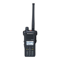
Motorola APX4000 XH User Manual (174 pages)
ASTRO APX 4000 Series TWO-WAY RADIOS
Brand:
Motorola
| Category:
Two-Way Radio
| Size: 7.73 MB
Table of Contents
Product View and Parts
3
Display Status Icons
4
Sending a Silent Emergency Call
4
Sending an Emergency Call
4
Declaration of Conformity
5
Table of Contents
7
Important Safety Information
14
RF Energy Exposure and Product Safety Guide for Portable Two-Way Radios
14
Software Version
15
Notice to Users (FCC and Industry Canada)
15
Informations Importantes Sur la Sécurité
16
Exposition aux Radiofréquences et Sécurité du Produit pour Radios Bidirectionnelles Portatives
16
Version du Logiciel
17
Avis aux Utilisateurs (FCC et Industrie Canada)
17
Computer Software Copyrights
18
Documentation Copyrights
18
Disclaimer
19
Getting Started
21
How to Use this Guide
21
Notations Used in this Manual
21
Additional Performance Enhancement
22
Dynamic System Resilience (DSR)
22
Crosstalk Prevention
22
Encrypted Integrated Data (EID)
22
Securenet
23
What Your Dealer/System Administrator Can Tell You
23
Preparing Your Radio for Use
24
Charging the Battery
24
Battery Charger
24
Attaching the Battery
25
Attaching the Antenna
26
Attaching the Accessory Connector Cover
26
Attaching the Belt Clip
27
Turning on the Radio
27
Adjusting the Volume
29
Identifying Radio Controls
29
Radio Parts and Controls
30
Programmable Features
31
Assignable Radio Functions
31
Assignable Settings or Utility Functions
33
Accessing the Preprogrammed Functions
34
Using the Menu Select Buttons
34
Using the Navigation Buttons
34
4-Way Navigation Button
34
Data Feature Button
34
Home Button
34
Multi Function Knob (MFK)
35
Using the Keypad
36
Keypad Characters - Uppercase Mode
36
Keypad Characters - Lowercase Mode
37
Keypad Characters - Numeric Mode
38
Keypad Characters - Hexadecimal Mode
39
Push-To-Talk (PTT) Button
40
Identifying Status Indicators
40
Status Icons
41
Text Messaging Service (TMS) Icons
44
Status Icons
44
TMS Menu Options
45
Call Type Icons
46
Top Lightbar and LED Indicators
47
LED Indications
47
Top Lightbar Indications
47
Intelligent Lighting Indicators
48
Alert Tones
49
Phone Call Display and Alert Prompts
53
General Radio Operation
54
Selecting a Zone
54
Selecting a Radio Channel
55
Using Channel Search Button
57
Using Mode Select Feature
58
Saving a Zone and Channel to a Softkey
58
Saving a Zone and Channel to a Keypad Button
59
Receiving and Responding to a Radio Call
59
Receiving and Responding to a Talkgroup Call
60
Receiving and Responding to a Private Call (Trunking Only)
60
Receiving and Responding to a Telephone Call (Trunking Only)
61
Making a Radio Call
62
Making a Talkgroup Call
62
Making a Private Call (Trunking Only)
62
Making an Enhanced Private Call (Trunking Only)
63
Making a Telephone Call (Trunking Only)
64
Repeater or Direct Operation
65
Monitoring Features
65
Monitoring a Channel
66
Conventional Mode Operation
66
Advanced Features
67
Advanced Call Features
67
Receiving and Making a Selective Call (ASTRO Conventional Only)
67
Receiving a Selective Call
67
Use this Navigation Guide to Learn more about Advanced Features Available with Your Radio: Advanced Call Features
67
Making a Selective Call
68
Using the Talkgroup Call Feature (Conventional Operation Only)
68
Selecting a Talkgroup
68
Sending a Status Call
69
Using the Dynamic Regrouping Feature (Trunking Only)
70
Requesting a Reprogram (Trunking Only)
70
Classifying Regrouped Radios
71
Using Dynamic Zone Programming (DZP)
71
Entering the Dynamic Zone to Select a Dynamic Channel
71
Saving a Channel in the Dynamic Zone from List Selection
71
Saving a Channel in the Dynamic Zone from Channel Name
72
Deleting a Channel in the Dynamic Zone
73
Contacts
73
Making a Private Call from Contacts
74
Adding a New Contact Entry
75
Deleting a Contact Entry
76
Adding a Contact to a Call List
77
Removing a Contact from a Call List
77
Editing a Contact in a Call List
78
Editing an Entry Alias
78
Editing as Entry ID
78
Editing a Call Type
79
Viewing Details of a Contact
79
Scan Lists
80
Viewing a Scan List
80
Editing the Scan List
80
Changing the Scan List Status
81
Viewing and Changing the Priority Status
81
Scan
82
Turning Scan on or off
82
Making a Dynamic Priority Change (Conventional Scan Only)
82
Deleting a Nuisance Channel
83
Restoring a Nuisance Channel
83
Call Alert Paging
84
Receiving a Call Alert Page
84
Sending a Call Alert Page
84
Emergency Operation
86
Sending an Emergency Alarm
86
Sending an Emergency Call (Trunking Only)
87
Sending an Emergency Alarm with Emergency Call
87
Sending a Silent Emergency Alarm
88
Using the Emergency Keep-Alive Feature
88
Man down
89
Pre-Alert Timer
90
Post-Alert Timer
90
Alerting User When man down Feature Is Triggered
90
Triggering Emergency
91
Exiting man down Feature
91
Re-Initiating man down
91
Testing the man down Feature
92
Automatic Registration Service (ARS)
93
Selecting or Changing the ARS Mode
93
Accessing the User Login Feature
94
Logging in as a User
94
Logging out
95
Text Messaging Service (TMS)
96
Accessing the TMS Features
96
Composing and Sending a New Text Message
97
Sending a Quick Text Message
98
Using the Priority Status and Request Reply
98
Using the Priority Status and Request Reply Features
100
Appending a Priority Status to a Text Message
100
Appending a Request Reply to a Text Message
100
Removing a Priority Status from a Text Message
100
Appending a Priority Status and a Reply Request to a Text Message
101
Removing a Request Reply from a Text Message
101
Removing a Priority Status and a Reply Request from a Text Message
102
Managing Text Messages
102
Receiving a Text Message
102
Replying to a Received Text Message
103
Viewing a Text Message from the Inbox
103
Accessing the Drafts Folder
104
Managing Sent Text Messages
105
Viewing a Sent Text Message
105
Deleting a Text Message
106
Sending a Sent Text Message
106
Deleting All Text Messages
107
ASTRO 25 Advanced Messaging Solution
107
System Setup for ASTRO Advanced Messaging Solution
108
Two-Factor Authentication
108
Logging into Two-Factor Authentication
109
Logging out of Two-Factor Authentication
110
Sending a Query
111
Receiving a Query
112
Secure Operations
113
Selecting Secure Transmissions
113
Selecting Clear Transmissions
113
Managing Encryption
113
Loading an Encryption Key
113
Using the Multikey Feature
114
Selecting a Keyset
115
Selecting an Encryption Key
115
Erasing the Selected Encryption Keys
116
Infinite UKEK Retention
117
MDC Over-The-Air Rekeying (OTAR) Page
117
Requesting an Over-The-Air Rekey (ASTRO Conventional Only)
117
Hear Clear
118
Security
118
Radio Lock
118
Unlocking Your Radio
118
Changing Your Password
119
Changing Your Tactical Inhibit Password
120
Enabling or Disabling the Radio Lock Feature (Secure Radios Only)
120
The Global Positioning System (GPS)
121
Understanding the GPS Feature
121
Enhancing GPS Performance
122
The Outdoor Location Feature (Using GPS)
122
Enabling MGRS Coordinates
122
Accessing the Outdoor Location Feature
123
Saving a Waypoint
124
Editing the Alias of a Waypoint
125
Viewing a Saved Waypoint
125
Editing the Coordinates of a Waypoint
126
Deleting a Single Saved Waypoint
127
Deleting All Saved Waypoints
128
Measuring the Distance and Bearing from a Saved Waypoint
128
Using the Location Feature While in Emergency Mode
129
Trunking System Controls
129
Using the Failsoft System
129
Going out of Range
130
Using the Site Trunking Feature
130
Locking and Unlocking a Site
130
Viewing and Changing a Site
131
Changing the Current Site
131
Viewing the Current Site
131
Mission Critical Wireless - Bluetooth
131
Turning the Bluetooth on
131
Turning the Bluetooth off
132
Re-Pair Timer
133
Bluetooth Drop Timer
134
Pairing Bluetooth Device with the Radio
134
Indicating Bluetooth Connection Is Lost
135
Turning on the Bluetooth Audio (Routing the Audio from the Radio to the Headset)
136
Turning off the Bluetooth Audio (Routing the Audio from the Headset to the Radio)
136
Adjusting the Volume of the Radio from Bluetooth Audio Device
137
Viewing and Clearing the Bluetooth Device Information
137
Clearing All Bluetooth Devices Information
138
Editing the Bluetooth Friendly Name
138
Programming over Project 25 (POP 25) (ASTRO 25 and ASTRO Conventional)
139
Responding to the Notification of Upgrade
139
Utilities
140
Viewing the Recent Calls
140
Selecting the Power Level
140
Selecting a Radio Profile
141
Enabling and Disabling the Radio Alias
142
Selecting the Audio Speaker
142
Controlling the Display Backlight
143
Setting up the Radio Display and Visual Indicators to Suite Night Vision Goggles
143
Locking and Unlocking the Keypad and Controls
144
Turning Keypad Tones on or off
144
Turning Voice Mute on or off
145
Using the Time-Out Timer
145
Editing the Time and Date
146
Setting the Time and Date
146
Analog Options
147
Digital Options
147
Using the Conventional Squelch Operation Features
147
Using the Digital PTT ID Feature
148
Using the PL Defeat Feature
148
Using the Smart PTT Feature (Conventional Only)
148
Accessing the Battery Info Screen
149
Accessing the General Radio Information
149
IMPRES™ Battery Annunciator
149
Procedure
149
Accessing the Radio Information
150
Viewing the Control Assignments
151
Viewing the IP Information
151
Editing the Soft ID
152
Voice Announcement
153
Motorola APX4000 XH User Manual (204 pages)
model 3
Brand:
Motorola
| Category:
Two-Way Radio
| Size: 7.17 MB
Table of Contents
Display Status Icons
4
Menu Navigation
4
Sending a Silent Emergency Call
4
Table of Contents
5
Declaration of Conformity
12
Important Safety Information
14
Software Version
15
Notice to Users (FCC and Industry Canada)
15
Consignes de Sécurité Importantes
16
Version Logicielle
17
Avis Aux Utilisateurs (FCC Et Industrie Canada)
17
Computer Software Copyrights
18
Documentation Copyrights
19
Disclaimer
20
Getting Started
21
How to Use this Guide
21
Notations Used in this Manual
21
Additional Performance Enhancement
22
ASTRO 25 Enhanced Data
22
Dynamic System Resilience (DSR)
22
Crosstalk Prevention
22
Encrypted Integrated Data (EID)
22
Securenet
22
Conventional Talkgroup and Radio Scan Enhancements
22
What Your Dealer/System Administrator Can Tell You
23
Preparing Your Radio for Use
24
Charging the Battery
24
Attaching the Battery
24
Attaching the Antenna
26
Removing and Attaching the Accessory Connector Cover
28
Attaching the Belt Clip
29
Turning on the Radio
31
Adjusting the Volume
33
Identifying Radio Controls
35
Radio Parts and Controls
35
Programmable Features
38
Assignable Radio Functions
38
Assignable Settings or Utility Functions
42
Accessing the Preprogrammed Functions
42
Menu Select Buttons
43
Home Button
43
4-Way Navigation Button
43
Data Feature Button
44
Multi-Function Knob (MFK)
44
Keypad
44
Keypad Characters - Uppercase Mode
45
Keypad Characters - Lowercase Mode
46
Keypad Characters - Numeric Mode
47
Keypad Characters - Hexadecimal Mode
48
Push-To-Talk (PTT) Button
49
Identifying Status Indicators
51
Status Icons
51
Text Messaging Service (TMS) Indicators
54
TMS Status Icons
54
TMS Menu Options
56
Call Type Icons
56
LED Indicator
57
Top Lightbar Indicator
58
Intelligent Lighting Indicators
59
Alert Tones
60
Phone Call Displays and Alerts
64
General Radio Operation
66
Selecting a Zone
66
Selecting a Radio Channel
66
Selecting a Channel Via Channel Search Button
68
Mode Select Feature
68
Saving a Zone and a Channel to a Softkey
69
Saving a Zone and a Channel to a Button
69
Receiving and Responding to a Radio Call
69
Receiving and Responding to a Talkgroup Call
70
Receiving and Responding to a Private Call (Trunking Only)
70
Receiving and Responding to a Telephone Call (Trunking Only)
71
Making a Radio Call
71
Making a Talkgroup Call
72
Making a Private Call (Trunking Only)
72
Making an Enhanced Private Call (Trunking Only)
73
Making a Telephone Call (Trunking Only)
74
Switching between Repeater or Direct Operation Button
75
Monitor Feature
76
Monitoring a Channel
76
Monitoring Conventional Mode
76
Advanced Features
78
Advanced Call Features
78
Selective Call (ASTRO Conventional Only)
78
Talkgroup Call Feature (Conventional Operation Only)
79
Sending a Status Call
80
Responding to the Dynamic Regrouping Feature (Trunking Only)
80
Dynamic Zone Programming (DZP)
82
Contacts
84
Making a Private Call from Contacts
85
Adding a New Contact Entry
86
Deleting a Contact Entry
87
Adding a Contact to a Call List
87
Removing a Contact from a Call List
88
Methods of Contact Editing in a Call List
88
Viewing Details of a Contact
90
Scan Lists
90
Viewing a Scan List
90
Editing the Scan List
90
Changing the Scan List Status
91
Viewing and Changing the Priority Status
92
Scan
93
Turning Scan on or off
93
Making a Dynamic Priority Change (Conventional Scan Only)
93
Deleting a Nuisance Channel
93
Restoring a Nuisance Channel
94
Call Alert Paging
94
Receiving a Call Alert Page
94
Sending a Call Alert Page
94
Emergency Operation
96
Sending an Emergency Alarm
97
Sending an Emergency Call (Trunking Only)
97
Sending an Emergency Alarm with Emergency Call
98
Sending a Silent Emergency Alarm
99
Change of Channels During Emergency
99
Emergency Keep-Alive Feature
99
Man down
100
Pre-Alert Timer
101
Post-Alert Timer
101
Radio Alerts When man down Feature Is Triggered
102
Triggering Emergency
102
Radio Alerts When man down Enhanced Is Triggered
102
Exiting man down Feature
103
Re-Initiating man down
103
Testing the man down Feature
103
Automatic Registration Service (ARS)
104
Selecting or Changing the ARS Mode
104
User Login Feature
105
Text Messaging Service (TMS)
107
Accessing the Messaging Features
107
Composing and Sending a New Text Message
108
Sending a Quick Text Message
109
Priority Status and Request Reply of a New Text Message
110
ASTRO 25 Advanced Messaging Solution
117
System Setup for ASTRO Advanced Messaging Solution
118
Two-Factor Authentication
118
Sending a Query
121
Receiving a Query
122
Secure Operations
123
Selecting Secure Transmissions
123
Selecting Clear Transmissions
123
Managing Encryption
123
Security
128
Radio Lock
128
Radio Stun and Kill
130
Radio Stun
130
Radio Kill
131
Global Positioning System (GPS)
132
GPS Operation
132
GPS Performance Enhancement
133
The Outdoor Location Feature (Using GPS)
133
Military Grid Reference System (MGRS) Coordinates
134
Accessing the Outdoor Location Feature
134
Saving a Waypoint
135
Viewing a Saved Waypoint
136
Editing the Alias of a Waypoint
137
Editing the Coordinates of a Waypoint
137
Deleting a Single Saved Waypoint
139
Deleting All Saved Waypoints
139
Measuring the Distance and Bearing from a Saved Waypoint
140
Location Feature in Emergency Mode
140
Peer-Location on the Display (ASTRO Conventional Only)
140
Geofence (ASTRO 25 Trunking System)
141
Entering the Geofence Area
142
Trunking System Controls
143
Using the Failsoft System
143
Out-Of-Range Radio
143
Site Trunking Feature
144
Locking and Unlocking a Site
144
Site Display and Search Button
144
Mission Critical Wireless - Bluetooth
145
Turning the Bluetooth on
145
Turning the Bluetooth off
146
Re-Pair Timer
147
Bluetooth Drop Timer
148
Pairing with Low Frequency-Motorola Proximity Pairing (LF-MPP) Feature
149
Radio Indications of Lost Bluetooth Connection
150
Standard Pairing Feature
150
PIN Authentication in Pairing
153
Turning on the Bluetooth Audio (Routing the Audio from the Radio to the Headset)
156
Turning off the Bluetooth Audio (Routing the Audio from the Headset to the Radio)
157
Adjusting the Volume of the Radio from Bluetooth Audio Device
157
Viewing and Clearing the Bluetooth Device Information
158
Clearing All Bluetooth Devices Information
158
Editing the Bluetooth Friendly Name
159
Programming over Project 25 (POP 25) (ASTRO 25 and ASTRO Conventional)
160
Responding to the Notification of Upgrade
160
Voice Announcement
161
Site Selectable Alerts (ASTRO 25)
162
Sending SSA Notification to Single Site
162
Sending SSA Notification to Single Site Via Manual Entry
163
Sending SSA Notification to All Sites
164
Sending SSA Notification to All Available Sites
164
Stopping SSA Notification of a Single Site
165
Stopping SSA Notification of a Single Site Via Manual Entry
166
Stopping SSA Notification of All Sites
166
Stopping SSA Notification of All Available Sites
167
Utilities
167
Viewing Recent Calls
167
Selecting the Power Level
168
Selecting a Radio Profile
169
Enabling and Disabling the Radio Alias
170
Selecting the Audio Speaker
170
Controlling the Display Backlight
171
Locking and Unlocking the Keypad and Controls
172
Turning the Controls and Keypad Buttons Tones on or off
172
Turning Voice Mute on or off
172
Using the Time-Out Timer
173
Time and Date Setup
173
Using Conventional Squelch Operation Features
174
Using the PL Defeat Feature
175
Digital PTT ID Support
175
Smart PTT Feature (Conventional Only)
176
Transmit Inhibit
176
IMPRES Battery Annunciator
178
General Radio Information
178
Advertisement
Motorola APX4000 XH User Manual (190 pages)
Brand:
Motorola
| Category:
Two-Way Radio
| Size: 5.15 MB
Table of Contents
Display Status Icons
4
Menu Navigation
4
Sending an Emergency Call
4
Table of Contents
5
Declaration of Conformity
12
Important Safety Information
14
Software Version
15
Notice to Users (FCC and Industry Canada)
15
Consignes de Sécurité Importantes
16
Version Logicielle
17
Avis Aux Utilisateurs (FCC Et Industrie Canada)
17
Computer Software Copyrights
18
Documentation Copyrights
19
Disclaimer
20
Getting Started
21
How to Use this Guide
21
Notations Used in this Manual
21
Additional Performance Enhancement
22
ASTRO 25 Enhanced Data
22
Dynamic System Resilience (DSR)
22
Crosstalk Prevention
22
Encrypted Integrated Data (EID)
22
Securenet
22
Conventional Talkgroup and Radio Scan Enhancements
22
What Your Dealer/System Administrator Can Tell You
23
Preparing Your Radio for Use
24
Charging the Battery
24
Attaching the Battery
24
Attaching the Antenna
25
Removing and Attaching the Accessory Connector Cover
26
Attaching the Belt Clip
27
Turning on the Radio
28
Adjusting the Volume
29
Identifying Radio Controls
30
Radio Parts and Controls
30
Programmable Features
31
Assignable Radio Functions
31
Assignable Settings or Utility Functions
35
Accessing the Preprogrammed Functions
35
Menu Select Buttons
36
Home Button
36
4-Way Navigation Button
36
Data Feature Button
36
Keypad
37
Keypad Characters - Uppercase Mode
37
Keypad Characters - Lowercase Mode
38
Keypad Characters - Numeric Mode
39
Keypad Characters - Hexadecimal Mode
40
Push-To-Talk (PTT) Button
42
Identifying Status Indicators
43
Status Icons
43
Text Messaging Service (TMS) Indicators
46
TMS Status Icons
46
TMS Menu Options
47
Call Type Icons
48
LED Indicator
48
Top Lightbar Indicator
50
Intelligent Lighting Indicators
50
Alert Tones
52
Phone Call Displays and Alerts
55
General Radio Operation
57
Selecting a Zone
57
Selecting a Radio Channel
57
Selecting a Channel Via Channel Search Button
58
Mode Select Feature
59
Saving a Zone and a Channel to a Softkey
59
Saving a Zone and a Channel to a Button
60
Receiving and Responding to a Radio Call
60
Receiving and Responding to a Talkgroup Call
60
Receiving and Responding to a Private Call (Trunking Only)
61
Receiving and Responding to a Telephone Call (Trunking Only)
62
Methods to Make a Radio Call
62
Making a Talkgroup Call
62
Making a Private Call (Trunking Only)
63
Making an Enhanced Private Call (Trunking Only)
64
Making a Telephone Call (Trunking Only)
65
Switching between Repeater or Direct Operation Button
66
Monitor Feature
66
Monitoring a Channel
66
Monitoring Conventional Mode
67
Advanced Features
68
Advanced Call Features
68
Selective Call (ASTRO Conventional Only)
68
Talkgroup Call Feature (Conventional Operation Only)
69
Sending a Status Call
69
Responding to the Dynamic Regrouping Feature (Trunking Only)
70
Dynamic Zone Programming (DZP)
72
Contacts
74
Making a Private Call from Contacts
75
Adding a New Contact Entry
76
Deleting a Contact Entry
77
Adding a Contact to a Call List
77
Removing a Contact from a Call List
78
Methods of Contact Editing in a Call List
78
Viewing Details of a Contact
80
Scan Lists
80
Viewing a Scan List
80
Editing the Scan List
80
Changing the Scan List Status
81
Viewing and Changing the Priority Status
82
Scan
82
Turning Scan on or off
83
Making a Dynamic Priority Change (Conventional Scan Only)
83
Deleting a Nuisance Channel
83
Restoring a Nuisance Channel
84
Call Alert Paging
84
Receiving a Call Alert Page
84
Sending a Call Alert Page
84
Quick Call II (ASTRO P25 Digital Trunking and Conventional)
86
Initiating a Quick Call II Transmission
87
Emergency Operation
87
Sending an Emergency Alarm
88
Sending an Emergency Call (Trunking Only)
88
Sending an Emergency Alarm with Emergency Call
89
Sending a Silent Emergency Alarm
90
Change of Channels During Emergency
90
Emergency Keep-Alive Feature
90
Man down
91
Pre-Alert Timer
92
Post-Alert Timer
93
Radio Alerts When man down Feature Is Triggered
93
Triggering Emergency
93
Radio Alerts When man down Enhanced Is Triggered
93
Exiting man down Feature
94
Re-Initiating man down
94
Testing the man down Feature
95
Automatic Registration Service (ARS)
95
Selecting or Changing the ARS Mode
95
User Login Feature
96
Text Messaging Service (TMS)
98
Accessing the Messaging Features
99
Composing and Sending a New Text Message
99
Sending a Quick Text Message
101
Priority Status and Request Reply of a New Text Message
102
ASTRO 25 Advanced Messaging Solution
109
System Setup for ASTRO Advanced Messaging Solution
110
Two-Factor Authentication
110
Sending a Query
113
Receiving a Query
114
Security
115
Radio Lock
115
Global Positioning System / Global Navigation Satellite System
117
GPS Operation
117
GPS Performance Enhancement
118
The Outdoor Location Feature (Using GPS)
118
Military Grid Reference System (MGRS) Coordinates
119
Accessing the Outdoor Location Feature
119
Saving a Waypoint
120
Viewing a Saved Waypoint
121
Editing the Alias of a Waypoint
121
Editing the Coordinates of a Waypoint
122
Deleting a Single Saved Waypoint
123
Deleting All Saved Waypoints
124
Measuring the Distance and Bearing from a Saved Waypoint
124
Location Feature in Emergency Mode
125
Peer-Location on the Display (ASTRO Conventional Only)
125
Geofence (ASTRO 25 Trunking System)
126
Entering the Geofence Area
127
Trunking System Controls
128
Operating in Failsoft System
128
Out-Of-Range Radio
128
Site Trunking Feature
129
Locking and Unlocking a Site
129
Site Display and Search Button
129
Mission Critical Wireless - Bluetooth
130
Turning on Bluetooth
130
Turning off the Bluetooth
131
Re-Pair Timer
132
Bluetooth Drop Timer
133
Pairing with Low Frequency-Motorola Proximity Pairing (LF-MPP) Feature
134
Radio Indications of Lost Bluetooth Connection
135
Standard Pairing Feature
135
PIN Authentication in Pairing
138
Turning on the Bluetooth Audio (Routing the Audio from the Radio to the Headset)
141
Turning off the Bluetooth Audio (Routing the Audio from the Headset to the Radio)
142
Adjusting the Volume of the Radio from Bluetooth Audio Device
142
Viewing and Clearing the Bluetooth Device Information
143
Clearing All Bluetooth Devices Information
144
Editing the Bluetooth Friendly Name
145
Over-The-Air Programming (POP 25, ASTRO 25, ASTRO Conventional)
145
Responding to the Notification of Upgrade
146
Voice Announcement
146
Site Selectable Alerts (ASTRO 25)
147
Sending SSA Notification to Single Site
148
Sending SSA Notification to Single Site Via Manual Entry
149
Sending SSA Notification to All Sites
150
Sending SSA Notification to All Available Sites
150
Stopping SSA Notification of a Single Site
151
Stopping SSA Notification of a Single Site Via Manual Entry
151
Stopping SSA Notification of All Sites
152
Stopping SSA Notification of All Available Sites
153
Utilities
153
Viewing Recent Calls
153
Selecting the Power Level
154
Selecting a Radio Profile
155
Enabling and Disabling the Radio Alias
156
Selecting the Audio Speaker
156
Controlling the Display Backlight
157
Locking and Unlocking the Keypad and Controls
158
Turning the Controls and Keypad Buttons Tones on or off
158
Turning Voice Mute on or off
158
Using the Time-Out Timer
159
Time and Date Setup
159
Using Conventional Squelch Operation Features
160
Using the PL Defeat Feature
161
Digital PTT ID Support
161
Smart PTT Feature (Conventional Only)
161
Transmit Inhibit
162
IMPRES Battery Annunciator
164
General Radio Information
164
Advertisement
Related Products
Motorola APX 4000Li
Motorola APX 400Li
Motorola APX 4000
Motorola ASTRO APX 4000 3
Motorola APX 4000Li 1
Motorola ASTRO APX 4000 Model 2
Motorola APX 400Li 1
Motorola APX 4000XH
Motorola APX 4500 O2 CH
Motorola APX 4000 2
Motorola Categories
Cell Phone
Two-Way Radio
Baby Monitor
Cordless Telephone
Radio
More Motorola Manuals
Login
Sign In
OR
Sign in with Facebook
Sign in with Google
Upload manual
Upload from disk
Upload from URL