Sign In
Upload
Manuals
Brands
Mitsubishi Manuals
Engine
S12A2
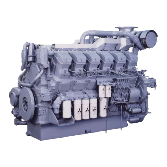
Mitsubishi S12A2 Manuals
Manuals and User Guides for Mitsubishi S12A2. We have
1
Mitsubishi S12A2 manual available for free PDF download: Service Manual
Mitsubishi S12A2 Service Manual (355 pages)
Brand:
Mitsubishi
| Category:
Engine
| Size: 38 MB
Table of Contents
Description Format
4
How to Use this Manual
4
Abbreviations and Standards
5
Terms Used in this Manual
5
Unit of Measurement
5
Fire and Explosion Precautions
6
Safety Cautions
6
Stay Away from Rotating and Moving Parts
7
Be Careful of Exhaust Gas Poisoning
8
Be Careful of Falling
8
Be Careful of Hearing Loss
8
Be Careful of Burns
9
Be Careful When Handling Fuel, Engine Oil or LLC
9
Be Careful with Battery
10
When Abnormality Occurs
10
Other Cautions
11
Cool down the Engine before Stop
12
Do Not Operate the Engine in an Overloaded Condition
12
Use Care to Protect Engine from Water
12
Warm-Up the Engine before Use
12
Be Careful of Engine Room Ventilation
13
Do Not Operate Starter for a Long Time
13
Do Not Touch High Pressure Fuel Jet
13
Do Not Turn off the Battery Switch During Operation
13
Warning Labels
14
Points on Disassembling and Assembling
15
General Contents
17
Table of Contents
19
General Information
19
Engine Front View - S12A2-PTA
21
Engine Rear View - S12A2-PTA
21
External View
21
Left Side View - S12A2-PTA
22
Right Side View - S12A2-PTA
22
Engine Front View - S12A2-PTA2
23
Engine Rear View - S12A2-PTA2
23
Left Side View - S12A2-PTA2
24
Right Side View - S12A2-PTA2
24
Engine Front View - S12A2-Y1PTA2
25
Engine Rear View - S12A2-Y1PTA2
25
Left Side View - S12A2-Y1PTA2
26
Right Side View - S12A2-Y1PTA2
26
Engine Front View - S12A2-PTK
27
Engine Rear View - S12A2-PTK
27
Left Side View - S12A2-PTK
28
Right Side View - S12A2-PTK
28
Engine Front View - S12A2-PTAW
29
Engine Rear View - S12A2-PTAW
29
Left Side View - S12A2-PTAW
30
Right Side View - S12A2-PTAW
30
Engine Front View - S12A2-Y2PTAW
31
Engine Rear View - S12A2-Y2PTAW
31
Left Side View - S12A2-Y2PTAW
32
Right Side View - S12A2-Y2PTAW
32
Chapter 1 GENERAL
33
Outline of Fuel System
33
Outline of Lubrication System
33
Outline of Cooling System
34
PTA,PTA2 Spec Radiator Cooling - Diagram
34
PTK, PTAW Spec External Cooling Type - Diagram
35
Y2PTAW Spec Two Way Pump System External Cooling - Diagram
35
MTK, MPTK Spec with Fresh Water Cooling System or Seawater Cooling System - Diagram
36
Outline of Inlet and Exhaust System
36
Contents of Plate and Label
37
Name Plate
37
Caution Plate
37
Emissions Certification Label
37
Specifications
38
Service Data
43
Chapter 2 SERVICE DATA
45
Maintenance Service Data of Engine General
45
Maintenance Service Data of Basic Engine
46
Maintenance Service Data of Fuel System
51
Maintenance Service Data of Lubrication System
55
Maintenance Service Data of Cooling System
56
Maintenance Service Data of Electrical System
59
Air Start System Service Data
62
Belt Tension
62
Tightening Torque Spec for Basic Engine
63
Tightening Torque Spec for Cooling System
64
Tightening Torque Spec for Inlet and Exhaust System
64
Tightening Torque Spec for Air Start System
65
Tightening Torque for Standard Bolts
66
Tightening Torque for Fuel Injection Pipe
67
Tightening Torque for Standard Union Nuts
67
Special Tools
71
Overhaul Instructions
77
Determining Overhaul Timing
79
Compression Pressure - Measure
80
Disassembly of Basic Engine
81
Chapter 5 DISASSEMBLY of BASIC ENGINE
83
Cylinder Heads and Valve Mechanisms - Disassemble and Inspect
83
Fuel Pipe - Remove
84
Nozzle Assembly - Remove
84
Valve Clearance - Inspect
84
Fuel Injection Timing - Inspect
85
Rocker Shaft Assembly - Remove
85
Clearance between Bottom Face of Valve Bridge and Top Face of Valve Rotator - Inspect
85
Valve Bridge - Remove
86
Cylinder Head Assembly - Remove
86
Valve Sinkage - Measure
86
Valve and Valve Spring - Remove
87
Nozzle Gland Stud Bolt and Bridge Guide - Remove
87
Fuel Connector - Remove
87
Rear Mechanism - Disassemble and Inspect
88
Flywheel Face and Radial Runout - Measure
89
Flywheel - Remove
89
Timing Gear Case - Remove
89
Timing Gear Backlash - Measure
90
Idler Gear End Play - Measure
90
Camshaft End Play - Measure
90
Idler Gear - Remove
91
Fuel Injection Pump Gear - Remove
91
Governor Drive and Fuel Injection Pump Accessory Drive - Remove
91
Camshaft Gear - Remove
92
Idler Shaft - Remove
92
Rear Plate - Remove
93
Front Mechanism - Disassemble and Inspect
94
Fan, Fan Bracket Assembly and Belt - Remove
95
Damper Face and Radial Runout - Measure
95
Front Pulley, Damper and Crankshaft Pulley - Remove
95
Front Cover - Remove
96
Cylinder Liner, Piston and Connecting Rod - Disassemble and Inspect
97
Piston Protrusion - Measure
98
Connecting Rod End Play - Measure
98
Hard Carbon Deposits on the Upper Part of Cylinder Liner - Remove
98
Connecting Rod Cap - Remove
98
Piston - Remove
99
Removing the Piston with Chain Block Lifting
99
Piston Ring - Remove
100
Removing the Piston with Pushing-Up the Connecting Rod Big End
100
Cylinder Liner - Remove
101
Cylinder Liner Flange Protrusion - Measure
101
Cylinder Liner Inside Diameter - Measure
101
Piston Pin and Piston - Remove
101
Crankcase, Crankshaft and Main Bearing - Disassemble and Inspect
102
Crankcase - Turn over (Upend)
103
Crankshaft End Play - Measure
103
Main Bearing Cap - Remove
103
Piston Cooling Nozzle - Remove
103
Crankshaft - Remove
104
Inspection and Repair of Basic Engine
105
Chapter 6 INSPECTION and REPAIR of BASIC ENGINE
107
Cylinder Head and Valve Mechanism - Inspect and Repair
107
Bushing Inside Diameter and Shaft Outside Diameter of Rocker - Measure
107
Rocker Bushing - Replace
107
Valve Stem Outside Diameter and Valve Guide Inside Diameter - Measure
108
Valve Guide - Replace
108
Valve Face - Inspect
109
Seat Width - Inspect
109
Valve Face - Reface
109
Valve Margin - Inspect
109
Valve Seat - Reface
110
Valve Seat - Remove (by Welding)
110
Valve Seat - Remove (with Valve Seat Puller)
110
Valve Seat - Replace
110
Valve Seat - Install
111
Valve and Valve Seat - Lap
112
Valve Bridge, Bridge Cap, Valve Cotter and Valve Rotator - Inspect
112
Nozzle Gland Stud Bolt and Bridge Guide - Inspect and Replace
113
Push Rod Runout - Measure
113
Squareness and Free Length of Valve Spring - Measure
113
Tappet - Inspect
113
Distortion of Cylinder Head Bottom Surface - Measure
114
Water Director - Inspect and Replace
114
Rear Mechanism - Inspect and Repair
115
Cam Lift of Cam Shaft Lobe - Measure
115
Idler Bushing - Replace
115
Idler Bushing Inside Diameter and Idler Shaft Outside Diameter - Measure
115
Camshaft Bushing - Inspect
116
Camshaft Journal Outside Diameter - Measure
116
Camshaft Runout - Measure
116
Camshaft Bushing - Replace
117
Damper - Inspect Visually
118
Front Mechanism - Inspect and Repair
118
Pulley - Inspect
118
Piston - Inspect Visually
119
Piston and Connecting Rod - Inspect and Repair
119
Piston Outside Diameter - Measure
119
Piston Ring Groove - Inspect
119
Piston Weight
119
Piston Pin Bore Inside Diameter - Measure
120
Piston Ring - Inspect Visually
120
Piston Ring End Gap - Measure
120
Connecting Rod Bushing Inside Diameter - Measure
121
Connecting Rod Bushing - Remove
122
Connecting Rod Bushing - Press-In
123
Bore Diameter and Roundness of Connecting Rod Big End - Measure
124
Connecting Rod Assembly Weight Rank
124
Connecting Rod Bearing - Inspect
125
Connecting Rod Big End Serration and Bolt Holes - Inspect
125
Side Face Width of Connecting Rod Big End - Measure
125
Connecting Rod Bearing Thickness - Measure
126
Connecting Rod Bend and Twist - Inspect
126
Deflection of Connecting Rod - Measure
126
Crankcase and Crankshaft - Inspect and Repair
127
Crankcase Top Surface Distortion - Measure
127
Inside Diameter of Main Bearing Housing Bore - Measure
127
Counterbore in Crankcase - Repair
128
Crankpin and Journal Outside Diameters - Measure
128
Cylinder Liner Fitting Bore in Crankcase - Inspect
128
Crankpin and Crank Journal - Grind
129
Rearmost Crank Main Journal Width - Grind
130
Width of Crankpin and Rearmost Crank Main Journal - Measure
130
Crankshaft Runout - Measure
131
Crankshaft Gear - Inspect
132
Crankshaft Gear - Install
132
Crankshaft Gear - Remove
132
Crankshaft Gear - Replace
132
Oil Seal Slinger - Inspect
133
Oil Seal Slinger - Install
133
Oil Seal Slinger - Replace
133
Main Bearing - Inspect
134
Thickness of Main Bearing Shell - Measure
134
Thrust Plate - Inspect
134
Piston Cooling Nozzle - Inspect
135
Thickness of Thrust Plate - Measure
135
Oil Seal Slinger - Remove
133
Assembly of Basic Engine
137
Chapter 7 ASSEMBLY of BASIC ENGINE
139
Crankcase - Turn over (Upend)
139
Upper Main Bearing - Install
140
Crankshaft - Install
141
Upper Thrust Plates - Install
141
Lower Main Bearing Shell and Lower Thrust Plate - Install
141
Main Bearing Cap - Install
142
Crankshaft End Play - Measure
143
Crankcase - Turn over
143
Crankshaft and Main Bearing - Install
139
Piston Cooling Nozzle - Install
139
Cylinder Liner, Piston and Connecting Rod - Assemble
144
Cylinder Liner Protrusion - Measure
144
Cylinder Liner Flange Protrusion - Calculate (When Cylinder Liner Not Installed)
144
Cylinder Liner - Install
146
Cylinder Liner Flange Protrusion - Measure (When Cylinder Liner Installed)
146
Piston and Connecting Rod - Assemble
147
Cylinder Liner Inside Diameter - Measure
147
Piston Ring - Install
148
Crankshaft - Turn
148
Piston Installation - Prepare
149
Upper Connecting Rod Bearing - Install
149
Piston - Install
150
Connecting Rod Cap - Install
152
Connecting Rod End Play - Measure
153
Piston Protrusion - Measuring
153
Front Mechanism - Assemble
154
Front Oil Seal - Install
154
Crankshaft Pulley, Damper and Front Pulley - Install
155
Damper Face and Radial Runout - Measuring
155
Pointer - Install and Adjust
155
Rear Mechanism - Assemble
156
Idler Shaft - Install
156
Rear Plate - Install
156
Camshaft End Play - Measuring
157
Fuel Injection Pump Gear - Install
158
Governor Drive and Fuel Injection Pump Accessory Drive - Install
158
Idler Gear - Install
159
Camshaft Gear - Install
157
Idler Gear End Play - Measuring
159
Timing Gear Backlash - Measuring
160
Timing Gear Case - Install
160
Flywheel - Install
161
Rear Oil Seal - Install
161
Flywheel Face and Radial Runout - Measuring
161
Pickup - Install (Electronic Governor Spec)
162
Cylinder Head and Valve Mechanism - Assemble
163
Cylinder Head - Assemble
163
Liquid Gasket - Apply
164
Tappet - Install
164
Valve Sinkage - Measuring
164
Cylinder Head Assembly - Install
165
Cylinder Head Gasket - Install
165
Cylinder Head Bolt - Tighten
166
Bridges and Bridge Caps - Install
167
Clearance between Bottom Face of Valve Bridge and Top Face of Valve Rotator - Inspection
167
Valve Bridge and Adjusting Screw - Adjust
167
Rocker Shaft Assembly - Assemble
168
Rocker Shaft Assembly - Install
168
Fuel Injection Timing - Check and Adjust
169
Valve Clearance - Check and Adjust
169
Fuel Injection Timing - Adjust
170
Fuel Injection Timing - Check
170
Valve Timing - Inspect
171
Valve Timing When Valve Clearance Is 2 MM [0.08 In.]
171
Fuel Injection Nozzle Assembly - Install
172
Fuel Pipe - Install
172
Fuel System
173
Chapter 8 FUEL SYSTEM
175
Fuel Injection Pipe - Remove and Inspect
175
Fuel Leak-Off Pipe and Fuel Pipe - Remove and Inspect
176
Return to Fuel Injection Pump
177
Fuel Filter and Fuel Pipe - Remove and Inspect
178
Stop Solenoid - Remove and Inspect
179
Stop Solenoid RUN off Type
180
Fuel Control Link - Remove and Inspect
181
Woodward PROACT Type Actuator Spec
182
Toho Seisakusho SG4017 Type Actuator PTA2 Spec
183
Fuel Injection Pump - Remove and Inspect
184
Tamper Proof Attachment Spec
185
Fuel System - Remove and Inspect
175
Fuel System - Disassemble, Inspect and Assemble
186
Fuel Filter (Wire Element) - Disassemble, Inspect and Assemble
186
Fuel Filter (Paper Element) - Disassemble, Inspect and Assemble
187
Changeover Spec
188
Fuel Filter Cartridge - Install
189
Fuel Injection Nozzle - Disassemble and Inspect
190
Screw Adjust Type
191
Fuel Injection Nozzle - Inspect and Adjust
192
Fuel Injection Start Pressure - Inspect and Adjust
192
Valve Opening Pressure of Fuel Injection Nozzle - Adjust (Diagram)
192
Fuel Injection Nozzle Spray - Inspect
193
Nozzle Tip - Clean and Replace
193
Push Rod - Inspect
193
Spacer - Inspect
194
Fuel Injection Nozzle - Assemble
195
Fuel Injection Pump Accessory Drive - Disassemble and Inspect
197
Outside Diameter and Inside Diameter of Accessory Drive Bearing Fit - Inspect
198
Fuel Injection Pump Accessory Drive - Assemble
199
Governor Drive - Disassemble and Inspect
200
Outside Diameter and Inside Diameter of Bearing Fit
201
Governor Drive - Assemble
203
Backlash - Measure
203
Drive Gear and Case - Assemble
204
Fuel System - Install
205
Rubber - Install
204
Fuel Injection Pump - Install
205
Assembling Position of Fuel Injection Pump Coupling
207
Checking before Installing Fuel Injection Pump
207
Drive Coupling - Install
207
Pointer and Line Mark - Align
207
Coupling Distance - Adjust
208
Couplings and Plates - Assemble (Diagram)
208
Engine Oil - Refill (Diagram)
208
Fuel Injection Pump - Installation
208
Control Link Lever - Install
209
Control Shaft - Install
209
Fuel Control Link - Install
209
Fuel Control Link - Install and Adjust
210
Left-Bank Linkage - Overall View
210
Fixed-Length Control Links of Right and Left Banks
211
Left Bank Variable-Length Control Link
211
Right-Bank Linkage - Overall View
211
Fuel Control Link - Installation and Adjustment
213
Right and Left-Bank Control Links - Diagram
214
Stopper - Install
215
Stop Solenoid - Install
216
Stop Solenoid (RUN on Type) - Adjust
216
Solenoid Function - Verify
217
Stop Solenoid (RUN off Type) - Adjust
217
Lubrication System
219
Chapter 9 LUBRICATION SYSTEM
221
Oil Pipe - Remove
221
Oil Pipe for Fan Drive - Remove
222
Oil Cooler and Oil Filter - Remove and Inspect
223
Breather - Remove and Inspect
226
Oil Level Gauge and Oil Filler - Remove and Inspect
227
Oil Filter for Governor - Remove and Inspect
228
Oil Pan, Oil Strainer and Oil Pump - Remove and Inspect
229
Lubrication System - Remove and Inspect
221
Lubrication System - Disassemble, Inspect and Assemble
231
Oil Strainer - Disassemble and Inspect
231
Oil Pump and Safety Valve - Disassemble and Inspect
232
Oil Pump and Safety Valve - Inspect
233
Drive Gear and Driven Gear Backlash - Measure
233
Drive/Driven Gear Shaft Outside Diameters and Bushing Inside Diameters - Measure
233
Side Clearance between Gear Width and Case - Measure
233
Oil Pump Bushing - Insert (Diagram)
234
Oil Pump Bushing - Replace
234
Oil Pump Bushing Joint Position (Diagram)
234
Oil Pump Safety Valve - Inspect
234
Oil Pump and Safety Valve - Assemble
235
Oil Cooler, Oil Filter, and Relief Valve - Disassemble and Inspect
236
Oil Filter Alarm - Inspect
237
Relief Valve - Inspect
237
Relief Valve Opening Pressure - Measure
237
Bypass Valve - Inspect
238
Oil Cooler - Inspect
238
Oil Filter Cartridge - Install
238
Oil Filter, Relief Valve and Oil Cooler - Assemble
238
Bypass Oil Filter - Disassemble and Inspect
239
Governor Oil Filter - Disassemble and Inspect
240
Lubrication System - Install
241
Backlash When Installing Oil Pump - Adjust
241
Oil Pan - Install
241
Oil Pump, Oil Strainer and Oil Pan - Install
241
Cooling System
243
Chapter 10 COOLING SYSTEM
245
Tension Pulley - Remove and Inspect (Water Pump Side)
245
Tension Pulley - Remove and Inspect (Fan Side)
246
Thermostat Case and Water Pipe - Remove and Inspect
247
Water Pipe - Remove and Inspect (PTA,PTA2 Spec)
248
Water Pipe - Remove and Inspect (PTK Spec)
249
Water Pipe - Remove and Inspect (MPTA,C2MPTK Spec)
250
Water Pipe - Remove and Inspect (MPTK Spec)
251
Water Pipe - Remove and Inspect (PTAW Spec)
252
Heat Exchanger and Water Pipe - Remove and Inspect
253
Sea Water Pump and Water Pipe - Remove and Inspect
254
Expansion Tank and Water Pipe - Remove and Inspect
255
Water Pump and Water Pipe - Remove and Inspect
256
Cooling System - Remove and Inspect
245
Cooling System - Disassemble, Inspect and Assemble
257
Tension Pulley - Disassemble and Inspect (Water Pump Side)
257
Inner Ball Bearing - Insert
258
Outer Ball Bearing - Insert
258
Tension Pulley - Assemble
258
Tension Pulley - Insert
258
Bolt - Tighten
259
Snap Ring - Install
259
Thrust Plate - Install
259
Tension Pulley - Disassemble and Inspect (Water Pump Side for Air Cooler)
260
Spacer and Bolt - Install
261
Tension Pulley - Assembling
261
Tension Pulley - Disassemble and Inspect (Water Pump Side PTA2 Spec)
263
Tension Pulley - Inspect
263
Tension Pulley Assembling
264
Tension Pulley - Disassemble and Inspect (Fan Side PTA2 Spec)
265
Tension Pulley Inspecting
265
Tension Pulley Assembling Steps
266
Thermostat - Disassemble and Inspect
267
Thermostat - Inspect
268
Thermostat Motion Diagram
268
Heat Exchanger - Disassemble and Inspect
269
Heat Exchanger Element - Clean
269
Water Pump - Disassemble and Inspect
270
Impeller - Remove
271
Water Pump Mounted on Engine - Inspect
271
Water Pump Pulley - Remove
271
Water Pump Shaft - Remove
271
Water Pump - Inspect
272
Water Pump - Assemble
273
Ball Bearing - Install
274
Oil Seal - Install
274
Outer Oil Seal - Install
274
Unit Seal (Stationary Side) - Install
274
Water Pump for Air Cooler Cooling - Disassemble and Inspect
275
Impeller Removal
276
Water Pump for Air Cooler Cooling - Disassembling and Inspection
276
Water Pump Shaft Removal
276
Water Pump for Air Cooler Cooling - Inspect
277
Water Pump for Air Cooler Cooling - Assemble
278
Ball Bearing - Installation
279
Unit Seal - Install
279
Water Pump Shaft - Install
279
Sea Water Pump - Disassemble and Inspect
280
Outside Diameter and Inside Diameter of Bearing Fit - Inspect
281
Sea Water Pump - Assemble
282
Bearing - Install
283
Cam - Install
283
Oil Seal - Installation
283
Unit Seal (Stationary Side) - Installation
283
Bushing - Install
284
Case - Install
284
Shaft and Bearing - Install
284
Snap Ring - Installation
284
Cover - Install
285
Impeller - Install
285
Fan Drive Assembly - Disassemble and Inspect
286
Fan Drive - Inspect
287
Oil Seal Sleeve - Inspect
288
Oil Seal Sleeve - Install
288
Oil Seal Sleeve - Replace
288
Fan Drive - Assemble
289
Oil Seal Sleeve - Remove
288
Inner Ball Bearing Inserting
290
Oil Seal Installation
290
Outer Ball Bearing Inserting
290
Fan - Assemble
291
Fan Installation Direction
291
Cooling System - Install
292
Fan Pulley - Lock
291
Tension Pulley - Install
292
Water Outlet Pipe - Install
292
Water Pipe (Air Cooler) - Install
292
Inlet and Exhaust Systems
293
Chapter 11 INLET and EXHAUST SYSTEMS
295
Inlet and Exhaust Systems - Remove and Inspect
295
Air Duct and Air Cooler - Remove and Inspect (PTA,PTK,MPTA Spec)
295
Air Duct and Air Cooler - Remove and Inspect (PTA2 Spec)
296
Air Duct and Air Cooler - Remove and Inspect (MTK,MPTK Spec)
297
Pre-Cleaner and Paper Type Air Cleaner - Remove and Inspect
298
Air Cleaner - Remove and Inspect (with Air Cleaner PTA Spec 1)
299
Air Cleaner - Remove and Inspect (with Air Cleaner PTA Spec 2)
300
Exhaust Pipe - Remove and Inspect
301
Exhaust Manifold - Remove and Inspect
302
Inlet and Exhaust Systems - Disassemble, Inspect and Assemble
303
Air Cooler - Disassemble, Inspect and Assemble (PTA,PTK,PTAW,MPTA Spec)
303
Air Cooler - Disassemble, Inspect and Assemble (PTA2 Spec)
304
Air Cooler - Disassemble, Inspect and Assemble (MTK,MPTK Spec)
305
Air Cooler - Clean
306
Air Cooler - Inspect
306
Air Cooler - Assemble
307
Pre-Cleaner - Clean
307
Inlet and Exhaust Systems - Install
308
Air Cooler - Inspect for Leakage
307
Exhaust Manifold - Install
308
Exhaust Manifold Coupling - Tighten
308
Air Start System
309
Air Start System - Remove and Inspect
311
Chapter 12 AIR START SYSTEM
311
Magnetic Valve - Remove and Inspect
311
Air Pipe, Starter Valve and Distributor Valve - Inspect
312
Air Starter - Remove and Inspect
313
Air Start System - Disassemble, Inspect and Assemble
314
Starter Valve - Disassemble and Inspect
314
Starter Valve - Inspect
315
Clearance between Starter Valve and Starter Valve Guide - Measure
315
Free Length of Valve Spring - Measure
315
Starter Valve - Assemble
316
Distributer Valve - Disassemble and Inspect
317
Clearance between Distributer Shaft and Bushing - Measure
318
Distributer Valve - Inspect
318
Distributer Valve Height - Measure
318
Distributer Valve - Assemble
319
Air Start System - Install
319
Adjustment and Operation
321
Chapter 13 ADJUSTMENT and OPERATION
323
Engine - Adjust
323
Valve Bridge and Adjusting Screw - Check
323
Fuel System - Bleed Air
323
Fuel Filter (Wire Mesh Element Spec) - Bleed Air
323
Fuel Injection Timing - Check
323
Valve Clearance - Check
323
Air Filter (Change over Spec) - Bleed Air
324
Fuel Filter (Standard Spec) - Bleed Air
324
Fuel Injection Pump - Bleed Air
324
Priming Pump Cap - Lock
325
Priming Pump Cap Packing
325
Belt and Belt Tension - Inspect and Adjust
326
Belt - Inspect
326
Belt Tension (Fan) - Adjust
326
Fan Belt (Ribbed Belt Drive) Tension - Adjust
326
Belt Tension (Water Pump) - Adjust
327
Belt Tension - Adjust (Water Pump for Air Cooler)
327
Belt Tension (Alternator) - Adjust
328
Alternator Belt (V-Belt Drive) Tension - Adjust
328
Alternator Belt (Ribbed Belt Drive) Tension - Adjust
328
Ribbed Belt Tension (N) Table
329
Break-In Operation
330
Break-In Operation Load and Time
330
Engine Start-Up
330
Preparation before Engine Starting
330
Inspection and Adjustment after Break-In Operation
331
Engine-Test and Adjustment
332
Inspection While the Engine Is Running
331
Alarm Action and Emergency Stop Tests
332
Emission Gas Test
332
Engine Performance Test
332
Maximum Fuel Injection Volume - Set
332
Sealing after Tests and Adjustments Are Completed
333
Tamper Proof - Install
333
Tamper Proof - Remove
333
Engine Inspection Record Sheet (SA Series)
335
Inspection Record Sheet
336
Advertisement
Advertisement
Related Products
Mitsubishi S12U
Mitsubishi S12A2-PTA2
Mitsubishi S12R
Mitsubishi S12R-Y1PTA
Mitsubishi S 12 R
Mitsubishi S12R-T2MPTK
Mitsubishi S16R
Mitsubishi S16R2 Series
Mitsubishi S16R-PTA-C
Mitsubishi S16R2-PTAW-C
Mitsubishi Categories
Air Conditioner
Controller
Projector
Automobile
Engine
More Mitsubishi Manuals
Login
Sign In
OR
Sign in with Facebook
Sign in with Google
Upload manual
Upload from disk
Upload from URL