Sign In
Upload
Manuals
Brands
Meler Manuals
Industrial Equipment
MICRON+ GEAR Series
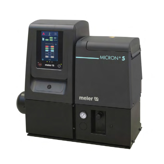
User Manuals: Meler MICRON+ GEAR Series Glue Melter
Manuals and User Guides for Meler MICRON+ GEAR Series Glue Melter. We have
2
Meler MICRON+ GEAR Series Glue Melter manuals available for free PDF download: Instruction Manual
Meler MICRON+ GEAR Series Instruction Manual (122 pages)
ADHESIVE MELTER
Brand:
Meler
| Category:
Industrial Equipment
| Size: 22 MB
Table of Contents
Table of Contents
3
1 Safety Guidelines
11
General
11
Symbols
11
Mechanical Components
12
Electrical Components
12
Hydraulic Components
12
Pneumatic Components
12
Thermal Components
13
Materials
13
Noise Emission Declaration
13
Intended Use
14
Limited Use
14
2 Introduction
15
Description
15
Modes of Operation
16
Hot-Melt Melter Identification
16
Main Components
17
Main Components de Micron+ Gear with Two Motor-Pumps
18
Control Panel Components
19
Automatic Feeder Main Components (Optional)
20
General
20
Micron+ Series Range
21
Optional Equipment
22
Automatic Feeder Option
22
Gas Injection Option
22
Air Dryer System
22
Bypass Valve Pressure Control System
22
Level Control System
22
Warning Light Option
22
Accessories
22
3 Installation
23
Introduction
23
Installation Requirements
23
Free Space
23
Electrical Consumption
24
Compressed Air
24
Other Factors
25
Unpacking
25
Contents
25
Mounting the Equipment
25
Electrical Power Connection
26
Pneumatic Connection
30
Hose and Applicator Connection
30
Parameter Programming
31
External I/O Connections
32
Connecting External Inputs and Outputs
34
Interpretation of External Inputs and Outputs
36
Connecting Zone Inhibition
38
External Signals of Pumping Control
39
Connection of Externar Singnals for Pumping Control
40
Automatic Feeder Assembly
41
Pneumatic Connection
41
Suction Tube Connection
42
Placing the Suction Tube
42
Electrical Connections
42
4 Melter Operation
43
General Information
43
Filling the Tank
43
Starting up the Melter Equipment
44
Manual Pumping Permmision
45
Melter Equipment Display
46
General Characteristics
47
Navigation Icons
47
Save Changes
47
Explanation of the Screen Contents
47
Home Display
48
General Temperature Status
48
Alarms Status
49
Calendar Status
49
Adhesive Level Status
49
Pumping Status
50
Temperature Status
50
Temperature and Heating Shortcut Displays
51
Programming of Temperatures
52
Programming of Statuses
52
Calendar
52
Units and Language Menu
53
Date and Time Configuration
53
Alarms and Warnings
53
Pumping Control Menu
54
Modes of Operation
56
Operating Mode with Internal Pumping Control and Internal Speed Control
56
Operating Mode with Internal Pumping Control and External Speed Control
57
Operating Mode with External Pumping Control and Internal Speed Control
58
Operating Mode with External Pumping Control and External Speed Control
59
Configuring Speed Ramp
60
Main Menu
60
Heating' Menu
61
Heating Zones
61
Sequential Heating
62
Inhibitions
62
Auto Standby - off
63
Extra Temperature Settings
64
General Settings' Menu
65
Password Management
65
Extra Settings
66
Configuration of Input and Output Signals
67
Restore Default Values
67
Menu '3. Pumping
68
Statistics' Menu
69
Charge' Menu
69
Screen 1: Minimum Adhesive Level Sensor
69
Screen 2: Automatic Adhesive Feeder
69
Screen 3: Dry Air/Gas Injection
70
Screen 4: Pressurisation (Only for Units with an Airtight Tank Lid)
70
Pumping Autolock' Function
71
Pumping Autolock' Enabled
71
Pumping Autolock' Disabled
72
Off after Reset' Function
73
Off after Resetting' Enabled
73
Off after Resetting' Disabled
74
Configuration of Turning on and Activating Pumping
74
Wireless Communication (Wi-Fi)
76
Connection Configuration
76
Standby Function
77
By-Pass Valve Regulation
78
Double Pressure Solenoid Valve (DP2- Optional)
78
Manual Valve Control
78
Adjust Pneumatic Valve Control (DP1 / DP2) (Optional)
79
Using the Air Drying System (Optional)
79
Turning off the Melter Equipment
79
Use of the Automatic Feeder
80
Start up and Automatic Process
80
Sensitivity Adjustment
81
Positioning of the Level Sensor
81
Application for PC
82
5 Maintenance
83
Equipment Cleaning
83
System Depressurisation
85
Access to the Interior of the Equipment
85
Access to Distributor
85
Access to Pump Gear- Motor
85
Filter Maintenance
86
Cleaning the Tank
87
Changing Adhesive Type
87
Cleaning Burnt Adhesive
87
Emptying the Tank
88
Pump Maintenance
89
Inspecting for Leaks
89
Gear Motor Maintenance
89
Cleaning the Motor Fan
89
Checking the Lubricant
89
Recommended Lubricants
90
Safety Thermostat
90
Pneumatic System Maintenance
90
Remove the Equipment from Its Base
91
Automatic Feeder Maintenance
92
Cleaning of the Unit
92
Pneumatic System
92
Control of the Load Sensor
93
Inspection of the Aspiration Tube
93
Filter Maintenance
93
Control of Pneumatic Vibrator
93
6 Technical Characteristics
95
Generals
95
Dimensions
97
7 Electrical Drawings
99
8 Pneumatic Diagram
101
Components List
101
Pneumatic By-Pass Valve Control System (Optional)
101
Air Drying System (Optional)
101
Double Pressure System (Opcional)
102
9 Spare Parts List
103
Distributor Unit
105
Distributor Simple/ Double Assembly
108
Geared Motor-Pump Assembly
109
Chassis Assembly
110
Electric Assembly
111
Electronic Assembly
112
Pneumatic Components
113
Gas Injection Assembly (Optional)
113
Air Dryer Assembly (Optional)
114
Automatic Feeder. Filter- Sensor Assembly
115
Automatic Feeder. Suction Tube
116
Automatic Feeder. Valve Assembly
117
Ec Declaration of Conformity
119
(Only for Equipments with Wifi System Integrated)
121
Advertisement
Meler MICRON+ GEAR Series Instruction Manual (108 pages)
Adhesive Melter
Brand:
Meler
| Category:
Industrial Equipment
| Size: 4 MB
Table of Contents
Table of Contents
3
1 Safety Guidelines
9
General
9
Symbols
9
Mechanical Components
10
Electrical Components
10
Hydraulic Components
10
Pneumatic Components
10
Thermal Components
11
Materials
11
Noise Emission Declaration
11
Intended Use
12
Limited Use
12
2 Introduction
13
Description
13
Modes of Operation
14
Hot-Melt Melter/Applicator Identification
14
Main Components
15
Main Components de MICRON + Gear with Two Motor-Pumps
16
Control Panel Components
17
Automatic Feeder Main Components (Optional)
18
General
18
MICRON + Series Range
19
Micron+ Gear Range Option Accessories
20
Automatic Feeder Option
20
Gas Injection Option
20
Air Dryer System
20
Bypass Valve Pressure Control System
20
Level Control System
20
Warning Light Option
20
Optional Equipment
20
3 Installation
21
Introduction
21
Installation Requirements
21
Electrical Consumption
22
Compressed Air
22
Other Factors
23
Unpacking
23
Contents
23
Mounting the Equipment
23
Electrical Power Connection
24
Pneumatic Connection
25
Hose and Applicator Connection
26
Parameter Programming
26
External I/O Connections
27
Connecting External Inputs and Outputs
29
Connecting Zone Inhibition
30
External Signals of Pumping Control
31
Connection of Externar Singnals for Pumping Control
31
Automatic Feeder Assembly
32
Pneumatic Connection
32
Suction Tube Connection
32
Placing the Suction Tube
32
Electrical Connections
33
4 Melter Operation
35
General Information
35
Filling the Tank
36
Starting up the Melter Equipment
36
Manual Pumping Permmision
37
Melter Equipment Display
38
General Characteristics
39
Navigation Icons
39
Save Changes
39
Interpretación de las Pantallas
39
Home Display
40
General Temperature Status
40
Alarms Status
41
Calendar Status
41
Adhesive Level Status
41
Pumping Status
42
Temperature Status
42
Temperature and Heating Shortcut Displays
43
Programming of Temperatures
44
Programming of Statuses
44
Menú Calendars
44
Units and Lenguage Menu
45
Date and Time Configuration
45
Alarms and Warnings
45
Pumping Control Menu
46
Modes of Operation
47
Pumping Safety' Function Activated
47
Pumping Safety' Function Deactivated
47
Operating Mode with Internal Pumping Control and Internal Speed Control
48
Operating Mode with Internal Pumping Control and External Speed Control
49
Operating Mode with External Pumping Control and Internal Speed Control
50
Operating Mode with External Pumping Control and External Speed Control
51
Configuring Speed Ramp
52
Main Menu
52
Heating' Menu
53
Heating Zones
53
Sequential Heating
54
Inhibitions
54
Auto Standby - off
55
Extra Temperature Settings
56
General Settings' Menu
57
Password Management
57
Extra Settings
58
Configuration of Input and Output Signals
59
Restore Default Values
59
Load' Menu
60
Screen 1: Minimum Adhesive Level Sensor
60
Screen 2: Automatic Adhesive Feeder
60
Screen 3: Dry Air/Gas Injection
60
Screen 4: Pressurisation (Only for Units with an Airtight Tank Lid)
61
Statistics' Menu
61
Menu '5. Pumping
62
Standby Function
63
By-Pass Valve Regulation
64
Manual Valve Control
64
Adjust Pneumatic Valve Control(DP1 / DP2) (Optional)
65
Using the Air Drying System (Optional)
65
Turning off the Melter Equipment
65
Use of the Automatic Feeder
66
Start up and Automatic Process
66
Sensitivity Adjustment
67
Positioning of the Level Sensor
67
Application for PC
68
5 Maintenance
69
Equipment Cleaning
69
System Depressurisation
71
Access to the Interior of the Equipment
71
Access to Distributor
71
Access to Pump Gear- Motor
71
Filter Maintenance
72
Cleaning the Tank
73
Changing Adhesive Type
73
Cleaning Burnt Adhesive
73
Emptying the Tank
74
Pump Maintenance
75
Inspecting for Leaks
75
Gear Motor Maintenance
75
Cleaning the Motor Fan
75
Checking the Lubricant
75
Recommended Lubricants
76
Safety Thermostat
76
Air Dryer Filter Maintenance
76
Remove the Equipment from Its Base
77
Automatic Feeder Maintenance
78
Cleaning of the Unit
78
Pneumatic System
78
Control of the Load Sensor
79
Inspection of the Aspiration Tube
79
Filter Maintenance
79
Control of Pneumatic Vibrator
79
6 Technical Characteristics
81
Generals
81
Dimensions
83
Micron+ Gear Range Option Accessories
85
Automatic Feeder System
85
Air Drying System for Reactives Adhesives
85
Pneumatic By-Pass Valve Pressure Control System
85
Level Control System
85
Warning Light Option
85
Optional Equipment
86
Wheel System
86
7 Electrical Drawings
87
8 Pneumatic Diagram
89
Components List
89
Pneumatic By-Pass Valve Control System (Optional)
89
Air Drying System (Optional)
89
Double Pressure System (Opcional)
90
9 Spare Parts List
91
Tank Assembly
94
Distributor Unit
95
Distributor Simple/ Double Assembly
96
Geared Motor-Pump Assembly
97
Chassis Assembly
98
Electric Assembly
99
Electronic Assembly
100
Pneumatic Components
101
Gas Injection Assembly (Optional)
101
Air Dryer Assembly (Optional)
102
Automatic Feeder. Filter- Sensor Assembly
103
Automatic Feeder. Suction Tube
104
Automatic Feeder. Valve Assembly
105
Ec Declaration of Conformity
107
Advertisement
Related Products
Meler Micron Gear Series
Meler Micron Mod
Meler MACRO FOAM Series
Meler MICRON NON STOP
Meler ML-242-ST
Meler ML-260-ST
Meler ML-210-ST
Meler ML-225-ST
Meler Micron PUR LC
Meler Micron PUR MC
Meler Categories
Industrial Equipment
Melting Machines
Laboratory Equipment
Water Pump
Controller
More Meler Manuals
Login
Sign In
OR
Sign in with Facebook
Sign in with Google
Upload manual
Upload from disk
Upload from URL