Sign In
Upload
Manuals
Brands
Maxon Motor Manuals
Controller
EPOS4 50/5
Maxon Motor EPOS4 50/5 Manuals
Manuals and User Guides for Maxon Motor EPOS4 50/5. We have
2
Maxon Motor EPOS4 50/5 manuals available for free PDF download: Hardware Reference Manual
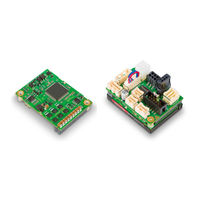
Maxon Motor EPOS4 50/5 Hardware Reference Manual (104 pages)
Positioning Controller
Brand:
Maxon Motor
| Category:
Controller
| Size: 14 MB
Table of Contents
T Cable Ofcontents 1 about 5
2
Table of Contents
2
1 About
5
About this Document
5
Table 3-43 Table
6
About the Devices
8
About the Safety Precautions
10
2 Specifications
11
Technical Data
11
Thermal Data
13
Limitations
14
Dimensional Drawings
14
Standards
16
3 Setup
17
Generally Applicable Rules
17
Pin Assignment for Module Version
18
Pin Assignment for Connector Boards & Compact Versions
21
EPOS4 CB 50/5 CAN (534133) / EPOS4 Compact 50/5 CAN (541718)
21
Cabling
21
Table 3-45 Table
21
Tools
22
Table 3-47 Table
22
Table 3-49 Table
22
Connections
23
Table 3-51 Table
24
Table 3-53 Table
24
Table 3-55 Table
25
Table 3-57 Table
25
Table 3-59 Table
25
Table 3-61 Table
26
Table 3-63 Table
26
DIP Switch Configuration (SW1)
35
Spare Parts
37
Connection Specifications
38
Power Supply
38
Logic Supply
39
Motor
40
Hall Sensor
41
Encoder
42
Sensor
44
Digital I/Os
55
Safe Torque off I/Os
59
Analog I/Os
61
3.4.10 Serial Communication Interface (SCI) / RS232
63
CAN Interface
65
Serial Peripheral Interface (SPI)
67
Usb (X13)
68
Status Indicators
69
4 Motherboard Design Guide
71
Requirements for Components of Third-Party Suppliers
72
Socket Headers
72
Supply Voltage
72
Logic Supply Voltage
73
Motor Cables and Motor Chokes
74
RS232 Transceiver
75
Recommended Components and Manufacturers
76
Design Guidelines
77
Ground
77
Layout
77
SMT Footprint
78
5 Wiring
79
Contents
79
DC Motors (Brushed)
80
DC Motor Without Sensor
80
DC Motor - Digital Incremental Encoder
81
DC Motor - Digital & Digital Incremental Encoder
82
DC Motor - Digital & Analog Incremental Encoder
83
DC Motor - Digital Incremental & SSI Encoder
84
DC Motor - Analog Incremental Encoder
85
DC Motor - SSI Encoder
86
EC Motors (BLDC, Brushless)
87
EC Motor - Hall Sensors
87
EC Motor - Hall Sensors & Digital Incremental Encoder
88
EC Motor - Hall Sensors & Analog Incremental Encoder
89
EC Motor - Hall Sensors & SSI Encoder
90
EC Motor - Hall Sensors & Digital & Digital Incremental Encoder
91
EC Motor - Hall Sensors & Digital & Analog Incremental Encoder
92
EC Motor - Hall Sensors & Digital Incremental & SSI Encoder
93
EC Motor - Digital Incremental & SSI Encoder
94
EC Motor - SSI Encoder
95
Advertisement
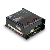
Maxon Motor EPOS4 50/5 Hardware Reference Manual (74 pages)
Positioning Controller
Brand:
Maxon Motor
| Category:
Controller
| Size: 6 MB
Table of Contents
T Cable Ofcontents 1 about 5
2
Table of Contents
2
1 About
5
About this Document
5
Figure 1-1 Documentation Structure
5
About the Device
7
About the Safety Precautions
8
2 Specifications
9
Technical Data
9
Thermal Data
11
Figure 2-2 Derating of Output Current
11
Limitations
12
Figure 2-3 Power Dissipation and Efficiency
12
Dimensional Drawing
13
Figure 2-4 Dimensional Drawing [MM]
13
Standards
14
3 Setup
15
Generally Applicable Rules
15
Cabling
16
Connections
18
Figure 3-5 Connectors
18
Power Supply (X1)
19
Figure 3-6 Power Supply Connector X1
19
Logic Supply (X2)
21
Figure 3-7 Logic Supply Connector X2
21
Motor (X3)
22
Figure 3-8 Motor Connectors X3
22
Hall Sensor (X4)
23
Figure 3-9 Hall Sensor Connector X4
23
Figure 3-10 Hall Sensor 1 Input Circuit (Analogously Valid for Hall Sensors 2 & 3)
24
Encoder (X5)
25
Figure 3-11 Encoder Connector X5
25
Figure 3-12 Encoder Input Circuit Ch a "Differential" (Analogously Valid for Ch B & Ch I)
26
Figure 3-13 Encoder Input Circuit Ch a "Single-Ended" (Analogously Valid for Ch B & Ch I)
27
Sensor (X6)
28
Figure 3-14 Sensor Connector X6
28
Figure 3-15 Digital Incremental Encoder Input Circuit Ch a "Differential" (Analogously Valid for Ch B)
29
Figure 3-16 Digital Incremental Encoder Input Circuit Ch I
30
Figure 3-17 Digital Incremental Encoder Input Circuit Ch a "Single-Ended" (Analogously Valid for Ch B)
31
Figure 3-18 Digital Incremental Encoder Input Circuit Ch I
32
Figure 3-19 Analog Incremental Encoder Input Circuit Ch a "Differential" (Analogously Valid for Ch B)
33
Figure 3-20 Analog Incremental Encoder Input Circuit Ch I (Digital Evaluation)
34
Figure 3-21 SSI Absolute Encoder Data Input
35
Figure 3-22 SSI Absolute Encoder Clock Output
35
Figure 3-23 Hsdigin1 Circuit "Differential" (Analogously Valid for Hsdigin2
36
Figure 3-24 Hsdigin1 Circuit "Single-Ended" (Analogously Valid for Hsdigin2
36
Figure 3-25 Hsdigout1 Output Circuit
37
Digital I/O (X7)
38
Figure 3-26 Digital I/O Connector X7
38
Figure 3-27 Digin1 Circuit (Analogously Valid for Digin2
39
Figure 3-28 Digin1 Circuit (Analogously Valid for Digin2
39
Figure 3-29 Digout1 Circuit (Analogously Valid for Digout2)
40
Figure 3-30 Digout1 "Sinks" (Analogously Valid for Digout2)
41
Figure 3-31 Digout1 "Source" (Analogously Valid for Digout2)
41
Analog I/O (X8)
42
Figure 3-32 Analog I/O Connector X8
42
Figure 3-33 Anin1 Circuit (Analogously Valid for Anin2)
43
Figure 3-34 Anout1 Circuit (Analogously Valid for Anout2)
43
Sto (X9)
44
Figure 3-35 STO Connector X9
44
Figure 3-36 STO-IN1 Circuit (Analogously Valid for STO-IN2)
45
Figure 3-37 STO-OUT Circuit
45
Rs232 (X10)
46
Figure 3-38 RS232 Connector X10
46
Can 1 (X11) & Can 2 (X12)
47
Figure 3-39 CAN 1 Connector X11 and CAN 2 Connector X12
47
Usb (X13)
49
Figure 3-40 USB Connector X13
49
Extension NET in (X14) & Extension NET out (X15)
50
Figure 3-41 Extension NET in & NET out Connectors X14 & X15
50
Extension Signal (X16)
52
Figure 3-42 Extension Signal Connector X16
52
Extension Slots (EXT1 & EXT2)
53
Figure 3-43 Extension Slots
53
DIP Switch Configuration (SW1)
54
Figure 3-44 DIP Switch SW1
54
3.3.17 Spare Parts
56
Status Indicators
57
Figure 3-45 Leds - Location
57
4 Wiring
59
Figure 4-46 Interfaces - Designations and Location
59
Possible Combinations to Connect a Motor
60
DC Motor
60
EC (BLDC) Motor
61
Figure 4-47 Main Wiring Diagram
62
Main Wiring Diagram
62
Excerpts
63
Power & Logic Supply
63
DC Motor
63
EC (BLDC) Motor
63
Hall Sensors
63
Figure 4-48 Power & Logic Supply
63
Figure 4-49 DC Motor
63
Figure 4-50 EC (BLDC) Motor
63
Figure 4-51 Hall Sensors
63
Digital Incremental Encoder
64
Digital & Digital Incremental Encoder
64
Digital & Analog Incremental Encoder
64
Figure 4-52 Digital Incremental Encoder
64
Figure 4-53 Digital & Digital Incremental Encoder
64
Figure 4-54 Digital & Analog Incremental Encoder
64
Digital Incremental & SSI Encoder
65
Analog Incremental Encoder
65
SSI Encoder
65
Figure 4-55 Digital Incremental & SSI Encoder
65
Figure 4-56 Analog Incremental Encoder
65
Figure 4-57 SSI Encoder
65
L Fist Ofigures
67
Advertisement
Related Products
Maxon Motor EPOS4 Module 50/8
Maxon Motor EPOS4 Compact 50/8 CAN
Maxon Motor EPOS4 Compact 50/8 EtherCAN
Maxon Motor EPOS4 Compact 50/5 CAN
maxon motor EPOS4 Module 24/1.5
maxon motor EPOS4 Module 24/1.5 CAN
maxon motor EPOS4 Module 50/5 CAN
maxon motor EPOS4 Compact 24/1.5 CAN
maxon motor EPOS4 CB 24/1.5 CAN
maxon motor EPOS4 Series
Maxon Motor Categories
Controller
DC Drives
Amplifier
Control Unit
Engine
More Maxon Motor Manuals
Login
Sign In
OR
Sign in with Facebook
Sign in with Google
Upload manual
Upload from disk
Upload from URL