Sign In
Upload
Manuals
Brands
Macurco Manuals
Carbon Monoxide Alarm
DVP-120
Macurco DVP-120 Manuals
Manuals and User Guides for Macurco DVP-120. We have
2
Macurco DVP-120 manuals available for free PDF download: User Instructions, Installation & Operating Instructions Manual
Macurco DVP-120 Installation & Operating Instructions Manual (37 pages)
Macurco DVP-120 Installation & Operating Instructions
Brand:
Macurco
| Category:
Carbon Monoxide Alarm
| Size: 0.57 MB
Table of Contents
Table of Contents
2
1 Introduction
5
General Information
5
Features
5
Compatible Macurco Transducers
5
Figure 1-1 System Wiring Diagram
6
Figure 1-2 DVP-120 Internal View
7
Specifications
8
Warranty
8
Return Instructions
8
2 Installation & Connection
9
Mounting the DVP-120
9
General Wiring Information
9
Main Power Connection
10
Remote Sensor Connection
10
Figure 2-1 Sensor Interface Connector
10
Table 2-1 Main Power Connections
10
Table 2-2 Recommended Wire Gauge
10
Table 2-3 Connector to Sensor Channel Mapping
11
Table 2-4 Sensor Connectors: Channel and Pin Assignments
11
Relay Connection
12
Figure 2-2 Relay Connector
12
Table 2-5 Relay Interface Signals and Connector Assignments
12
Horn & Strobe Connection
13
Figure 2-3 Horn & Strobe Connector
13
Table 2-6 Horn & Strobe Signals and Connector Assignments
13
Table 2-7 Wire Gauge for Horn & Strobe Functions
13
Interfacing Macurco Sensors
14
Table 2-8 Macurco Transducers
14
3 Operation
15
Initial Operating Mode
15
Status Light Display
15
Figure 3-1 Model Display
15
Figure 3-2 Warm-Up Display
15
User Interface
16
Figure 3-3 Keypad Layout
16
Normal Status Display
17
ALARM Status Display
17
Figure 3-4 Normal System Display
17
Figure 3-5 Sensor Prompt
17
Figure 3-6 Alarm Display
17
Warning Status Display
18
Trouble Status Display
18
Figure 3-7 Alarm Silenced Message
18
Figure 3-8 Warning Display
18
Figure 3-9 Warning Silenced Message
18
Figure 3-10 Trouble Display
18
Ventilation Control
19
Zone Signal Display
19
Figure 3-11 Trouble Silenced Message
19
Figure 3-12 Zone Signal Display
19
Figure 3-13 Zone Signal Silenced Message
19
Setting the System Configuration
20
Figure 3-14 Hardware Summary
20
Figure 3-15 Save Configuration? Prompt
20
Configure System Submenu
21
Figure 3-16 Set Time of Day
21
Figure 3-17 Enter Hours
21
Figure 3-18 Enter Minutes
21
System Menu
21
Figure 3-19 Set Day of the Week
22
Figure 3-20 Load Default Configuration
22
Figure 3-21 Enter Password
23
Figure 3-22 Password Prompt
23
Figure 3-23 Wrong Password Prompt
23
Configure Sensors Submenu
24
Figure 3-24 Sensor Summary
24
Figure 3-25 Sensor Type
24
Figure 3-26 Sensor's Alarm Level
24
Figure 3-27 Sensor's Warning Level
25
Figure 3-28 Sensor's Range
25
Configure Relays, Horn & Strobe Submenu
26
Figure 3-29 Relay Summary
26
Figure 3-30 Relay Mode
26
Figure 3-31 Turn on Delay
26
Figure 3-32 Minimum on Time
26
Configure Horn Submenu
27
Figure 3-33 Horn Summary
27
Figure 3-34 Horn Mode
27
Figure 3-35 Horn Turn on Delay
27
Figure 3-36 Horn Minimum on Time
27
Configure Strobe Submenu
28
Figure 3-37 Strobe Summary
28
Figure 3-38 Strobe Mode
28
Figure 3-39 Strobe Turn on Delay
28
Figure 3-40 Strobe Minimum on Time
28
Configure Zones Submenu
29
Figure 3-41 Zone Controls
29
Figure 3-42 Zone Group Type
29
Figure 3-43 Timer Days Selection
30
Figure 3-44 Start Time Selection
30
Figure 3-45 Stop Time Selection
30
Figure 3-46 Sensor Selection
30
Figure 3-47 Add/Remove Sensor Prompt
30
Figure 3-48 Rising Trip Point Entry
31
Figure 3-49 Falling Trip Point Entry
31
Figure 3-50 Sensor Mode Selection
31
Figure 3-51 Quorum Entry
31
Configure Signals Submenu
32
Figure 3-52 Alarm Signals
32
Figure 3-53 Buzzer Alarm Signal
32
Figure 3-54 Horn Alarm Signal
32
Figure 3-55 Strobe Alarm Signal
33
Figure 3-56 Warning Signals
33
Figure 3-57 Buzzer Warning Signal
33
Figure 3-58 Horn Warning Signal
33
Figure 3-59 Strobe Warning Signal
34
Figure 3-60 Trouble Signals
34
Figure 3-61 Buzzer Trouble Signal
34
Figure 3-62 Horn Trouble Signal
34
Figure 3-63 Strobe Trouble Signal
35
4 Troubleshooting
36
System Status Light Flashing
36
Input Channel Trouble
36
Internal Controller Board Trouble
36
Timed Ventilation Problem
36
No Power
37
LCD Display Unreadable
37
Hold the MENU Key for Three (3) Seconds
37
Press the up and down Cursor Keys to Change the LCD Contrast
37
Press any Other Key to Exit the Contrast-Setting Mode
37
The Keypad Does Not Respond (LCD Shows KEYS LOCKED)
37
After a Power Failure
37
Advertisement
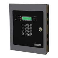
Macurco DVP-120 User Instructions (48 pages)
Detection and Ventilation Control Panel
Brand:
Macurco
| Category:
Control Panel
| Size: 3.83 MB
Table of Contents
Table of Contents
2
1 Introduction
4
General Information
4
DVP-120M Addressable Detection and Ventilation Control Panel
4
Macurco MRS-485 Modbus Adapter
4
Features
5
Specifications
5
2 Installation & Connection
5
Mounting the DVP-120
6
General Wiring Information
6
Main Power Connection
7
Remote Sensor Connection
8
Relay Connection
10
Horn & Strobe Connection
11
Interfacing Macurco Sensors
11
3 Operation
15
Initial Operating Mode
15
Status Light Display
16
User Interface
16
Normal Status Display
17
ALARM Status Display
17
Warning Status Display
18
Trouble Status Display
18
Ventilation Control
19
Zone Signal Display
19
Setting the System Configuration
19
System Menu
20
Configure System Submenu
21
Set Time of Day
21
Set Day of Week
21
Load Default Configuration
22
Change Password
22
Configure Sensor Type
23
Enter Password
25
Configure Sensors Submenu
25
Sensor Summary
25
Sensor Type
26
Alarm Set Point
26
Warning Set Point
26
Range
27
Configure Relays, Horn & Strobe Submenu
27
Relay Summary
27
Relay Mode
27
Relay Turn on Delay
27
Relay Minimum on Time
28
Configure Horn Submenu
28
Horn Summary
28
Horn Turn on Delay
28
Horn Minimum on Time
28
Configure Strobe Submenu
28
Strobe Summary
28
Strobe Turn on Delay
29
Strobe Minimum on Time
29
Configure Zones Submenu
29
Zone Controls
29
Zone Group Type
30
Timed Day Selection
30
Start Time
31
Stop Time
31
Sensor Selection
31
Rising Trip Point
31
Falling Trip Point
32
Multiple Sensor Mode
32
3.3.7.10 Multiple Sensor Quorum
32
Configure Signals Submenu
32
Alarm Signal Summary
32
Alarm Buzzer Signal
32
Alarm Horn Signal
33
Alarm Strobe Signal
33
Warning Signal Summary
33
Warning Buzzer Signal
34
Warning Horn Signal
34
Warning Strobe Signal
34
Trouble Signal Summary
34
3.3.8.10 Trouble Buzzer Signal
34
3.3.8.11 Trouble Horn Signal
35
3.3.8.12 Trouble Strobe Signal
35
4 Troubleshooting
35
System Status Light Flashing
35
Input Channel Trouble
35
No Sensor
36
Wrong Sensor Type
36
Sensor Trouble
36
Faulty Wiring
36
Resettable Fuse
36
Internal Controller Board Trouble
36
Timed Ventilation Problem
36
No Power
36
LCD Display Unreadable
37
The Keypad Does Not Respond (LCD Shows KEYS LOCKED)
37
The Keypad Does Not Respond after Silencing an Alarm, Warning or Trouble
37
After a Power Failure
37
Modbus Application
37
5 Macurco Gas Detection Products Limited Warranty
39
6 Appendix A Quick Set-Up
40
Advertisement
Related Products
Macurco DVP-120M
Macurco DVP-120C
Macurco DVP-485B
Macurco DVP-1200
Macurco DVP-120B
Macurco DMK-1
Macurco CM-6
Macurco CM-E1
Macurco Categories
Gas Detectors
Security Sensors
Carbon Monoxide Alarm
Control Panel
Controller
More Macurco Manuals
Login
Sign In
OR
Sign in with Facebook
Sign in with Google
Upload manual
Upload from disk
Upload from URL