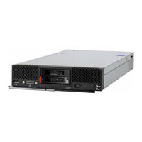
Sign In
Upload
Manuals
Brands
Lenovo Manuals
Server
Flex System x220
Lenovo Flex System x220 Manuals
Manuals and User Guides for Lenovo Flex System x220. We have
2
Lenovo Flex System x220 manuals available for free PDF download: Installation And Service Manual
Lenovo Flex System x220 Installation And Service Manual (714 pages)
Compute Node
Brand:
Lenovo
| Category:
Server
| Size: 14.94 MB
Table of Contents
Table of Contents
3
Safety
5
Safety Statements
6
Chapter 1. Introduction
9
Related Documentation
10
Brocade Documentation
10
The Lenovo Documentation CD
11
Hardware and Software Requirements
11
Using the Documentation Browser
11
Notices and Statements in this Document
12
Features and Specifications
13
What Your Compute Node Offers
14
Lenovo Xclarity Administrator
17
Reliability, Availability, and Serviceability Features
19
Major Components of the Compute Node
19
Power, Controls, and Indicators
20
Compute Node Controls, Connectors, and Leds
20
Console Breakout Cable
23
Turning on the Compute Node
23
Turning off the Compute Node
24
System-Board Layouts
25
System-Board Connectors
25
System-Board Jumpers
25
System-Board Leds
26
System-Board Switches
26
Chapter 2. Configuring
29
Updating Firmware and Device Drivers
29
Recovering a UEFI Image
30
Configuring the Compute Node
31
Using the Setup Utility
32
Nx Boot Failure
36
Setting the Boot Protocol to Boot from Legacy Devices Using the Setup Utility
37
Using the Boot Selection Menu Program
38
Updating the Universally Unique Identifier and DMI/SMBIOS Data
38
Remotely over a Lan
40
Configuring a RAID Array
41
Features on Demand
48
Setting up the LAN-On-Motherboard Feature
48
Chapter 3. Installing the Operating System
51
Using the Serverguide Setup and Installation CD
52
Serverguide Features
52
Typical Operating-System Installation
53
Installing the Operating System Without Using Serverguide
53
Using Lenovo Serverguide Scripting Toolkit
53
Chapter 4. Accessing the IMM2
55
Accessing the IMM2 Remotely
55
Viewing the Network Access Tag
55
Logging in to the IMM2 Web Interface
56
IMM2 Action Descriptions
57
Accessing the IMM2 Using the LAN over USB Interface
60
Potential Conflicts with the LAN over USB Interface
60
Resolving Conflicts with the IMM2 LAN over USB Interface
60
Configuring the LAN over USB Interface Manually
61
Chapter 5. Parts Listing, Types 2585 and 7906
63
Chapter 6. Troubleshooting
69
Service Bulletins
69
Diagnostic Tools
69
Light Path Diagnostics
69
IMM Event Log
71
Lenovo Dynamic System Analysis
73
Dsa Editions
74
DSA Diagnostic Test Results
75
Dsa System Management Test Results
180
Dsa Checkpoint Panel Test Results
194
Dsa Broadcom Network Test Results
196
Dsa Brocade Test Results
206
Event Messages
231
IMM Messages
231
UEFI Diagnostic Codes
592
Troubleshooting by Symptom
622
Compute Node Start Problems
623
Connectivity Problems
623
Hard Disk Drive Problems
636
Intermittent Problems
636
Intermittent Connectivity Problems
637
Memory Problems
638
Observable Problems
638
Optional Device and Replaceable Component Installation Problems
639
Performance Problems
640
Power-On Problems
640
Software Problems
642
Undetermined Problems
642
Collecting Service Data
643
Chapter 7. Installing, Removing, and Replacing Compute Node Components
645
Installing an Optional Device
645
Installation Guidelines
645
System Reliability Guidelines
645
Handling Static-Sensitive Devices
646
Returning a Device or Component
646
Updating the Compute Node Configuration
646
Removing a Compute Node from a Chassis
647
Installing a Compute Node in a Chassis
647
Removing and Replacing Consumable and Structural Parts
649
Removing the Chassis Bulkhead
649
Installing the Chassis Bulkhead
650
Removing the Compute Node Cover
651
Installing the Compute Node Cover
652
Removing the Front Handle
653
Installing the Front Handle
654
Removing the Hard Disk Drive Cage
655
Installing the Hard Disk Drive Cage
655
Removing and Replacing Tier 1 Customer Replaceable Units (Crus)
656
Removing the Bezel
656
Installing the Bezel
657
Removing the CMOS Battery
658
Installing the CMOS Battery
659
Removing a DIMM
660
Installing a DIMM
662
Removing a Fabric Connector
667
Installing a Fabric Connector
668
Removing the Hard Disk Drive Backplane
669
Installing the Hard Disk Drive Backplane
670
Removing a Hot-Swap Hard Disk Drive
671
Installing a Hot-Swap Hard Disk Drive
671
Removing a Serveraid Controller
672
Installing a Serveraid Controller
673
Removing an I/O Expansion Adapter
674
Installing an I/O Expansion Adapter
675
Removing the Light Path Diagnostics Panel
676
Installing the Light Path Diagnostics Panel
677
Removing the RFID Tag
678
Installing the RFID Tag
679
Removing the USB Flash Drive
679
Installing the USB Flash Drive
680
Removing and Replacing Tier 2 Customer Replaceable Units (Crus)
681
Removing the Adapter-Retention Assembly
681
Installing the Adapter-Retention Assembly
682
Removing a Microprocessor and Heat Sink
683
Installing a Microprocessor and Heat Sink
686
Thermal Grease
690
Removing the System-Board Assembly
691
Installing the System-Board Assembly
692
Appendix A. Getting Help and Technical Assistance
695
Before You Call
695
Using the Documentation
696
Getting Help and Information from the World Wide Web
696
How to Send DSA Data
696
Creating a Personalized Support Web Page
696
Software Service and Support
696
Hardware Service and Support
697
Taiwan Product Service
697
Appendix B. Notices
699
Trademarks
700
Important Notes
700
Recycling Information
700
Particulate Contamination
701
Telecommunication Regulatory Statement
701
Electronic Emission Notices
702
Federal Communications Commission (FCC) Statement
702
Industry Canada Class a Emission Compliance Statement
702
Avis de Conformité À la Réglementation D'industrie Canada
702
Australia and New Zealand Class a Statement
702
European Union EMC Directive Conformance Statement
702
Germany Class a Statement
703
Japanese Electromagnetic Compatibility Statements
704
Korea Communications Commission (KCC) Statement
704
Russia Electromagnetic Interference (EMI) Class a Statement
704
People's Republic of China Class a Electronic Emission Statement
704
Taiwan Class a Compliance Statement
704
Taiwan BSMI Rohs Declaration
705
Index
707
Advertisement
Lenovo Flex System x220 Installation And Service Manual (70 pages)
Flex System Storage Expansion Node
Brand:
Lenovo
| Category:
Storage
| Size: 2.67 MB
Table of Contents
Table of Contents
3
Safety
5
Safety Statements
6
Chapter 1. Introduction
9
Features and Specifications
9
Supported Compute Nodes
10
Major Components of the Storage Expansion Node
10
System Board
11
Interposer Cable
12
Drive Drawer
12
Control Panel
13
Notices and Statements in this Document
13
Chapter 2. Installing the Storage Expansion Node
15
Installation Guidelines
15
System Reliability Guidelines
15
Handling Static-Sensitive Devices
16
Removing the Cover from the Storage Expansion Node
16
Installing the Compute Node
17
Removing the Compute Node from the Storage Expansion Node Assembly
18
Installing a Flash/Raid Adapter and Flash Power Module
19
Completing the Installation
21
Installing the Cover on the Storage Expansion Node
21
Installing the Storage Expansion Node in an Flex System Enterprise Chassis
22
Updating the Compute Node Configuration
23
Configuring the RAID Controller
23
Installing a Hot-Swap Drive
24
Removing the Storage Expansion Node Assembly from the Flex System Enterprise Chassis
25
Chapter 3. Parts Listing - Storage Expansion Node
27
Chapter 4. Troubleshooting
29
Event Messages
29
Connection Failure
29
Light Path Diagnostics
30
Chapter 5. Removing and Replacing Components
33
Installation Guidelines
33
System Reliability Guidelines
33
Handling Static-Sensitive Devices
34
Returning a Device or Component
34
Removing and Replacing Structural Parts
34
Removing the Cover from the Storage Expansion Node
34
Installing the Cover on the Storage Expansion Node
35
Removing the Cam Handle
35
Replacing the Cam Handle
36
Removing the Expansion Shelf
37
Replacing the Expansion Shelf
39
Removing the Control Panel Assembly
41
Replacing the Control Panel Assembly
42
Removing the Bezel
42
Replacing the Bezel
43
Removing the Rear Bulkhead
43
Replacing the Rear Bulkhead
45
Removing and Replacing Tier 1 Customer Replaceable Units (Crus)
46
Removing the Flash/Raid Adapter
46
Replacing the Flash/Raid Adapter
47
Removing the Flash Power Module
48
Replacing the Flash Power Module
49
Removing the Storage Expansion Node from the Expansion Shelf
50
Replacing the Storage Expansion Node
52
Removing a Hot-Swap Drive
53
Replacing a Hot-Swap Drive
54
Appendix A. Getting Help and Technical Assistance
55
Before You Call
55
Using the Documentation
56
Getting Help and Information from the World Wide Web
56
How to Send DSA Data
56
Creating a Personalized Support Web Page
56
Software Service and Support
56
Hardware Service and Support
57
Taiwan Product Service
57
Appendix B. Notices
59
Trademarks
60
Important Notes
60
Recycling Information
60
Particulate Contamination
61
Telecommunication Regulatory Statement
61
Electronic Emission Notices
61
Federal Communications Commission (FCC) Statement
61
Industry Canada Class a Emission Compliance Statement
62
Avis de Conformité À la Réglementation D'industrie Canada
62
Australia and New Zealand Class a Statement
62
European Union EMC Directive Conformance Statement
62
Germany Class a Statement
62
Japan VCCI Class a Statement
63
Japan Electronics and Information Technology Industries Association (JEITA) Statement
63
Korea Communications Commission (KCC) Statement
64
Russia Electromagnetic Interference (EMI) Class a Statement
64
People's Republic of China Class a Electronic Emission Statement
64
Taiwan Class a Compliance Statement
64
Index
65
Advertisement
Related Products
Lenovo Flex System x240
Lenovo Flex System X6 Compute Node
Lenovo Flex System x440 Compute Node
Lenovo IdeaCentre Flex 20 Series
Lenovo ideapad FLEX 4-1580
Lenovo IdeaPad FLEX-14API
Lenovo Flex 7
Lenovo IdeaPad Flex 5 Chromebook
Lenovo ideapad FLEX 4-1480
Lenovo Flex 3-1570
Lenovo Categories
Laptop
Desktop
Server
Monitor
Tablet
More Lenovo Manuals
Login
Sign In
OR
Sign in with Facebook
Sign in with Google
Upload manual
Upload from disk
Upload from URL