Sign In
Upload
Manuals
Brands
JRC Manuals
Measuring Instruments
JLN-900
JRC JLN-900 Manuals
Manuals and User Guides for JRC JLN-900. We have
1
JRC JLN-900 manual available for free PDF download: Installation And Instruction Manual
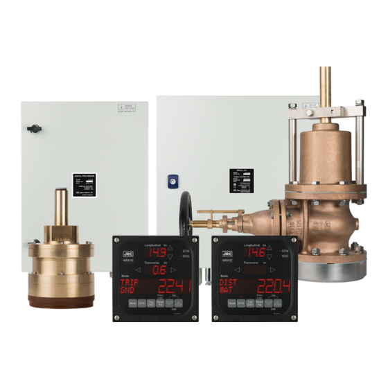
JRC JLN-900 Installation And Instruction Manual (308 pages)
SPEED LOG
Brand:
JRC
| Category:
Measuring Instruments
| Size: 6.61 MB
Table of Contents
Technical Description
18
Table of Contents
18
1 Principle of Operation
19
2 Speed over Ground Measurement
19
Acoustic Transmission/Reception
19
Depth Measurement
20
Seek Mode
20
Lock Mode
20
Speed Measurement
21
Speckle Pattern
21
Correlation Technique
26
3 Transducer
27
4 Sig.processor
28
Btu-Pcb
29
WTU-Assy
29
Data Transmission / Reception
29
Technical Specification
32
1 General
33
2 Performance
33
Principle of Operation
33
STW (Speed through the Water = Relative Speed)
33
SOG (Speed over the Ground = True Speed)
33
Accuracy of Measurement
33
Stw
33
Sog
33
Functional Limitations
34
Stw
34
Sog
34
3 Environmental Conditions
35
4 Interfaces
35
Serial Interface & Sentences
35
NQA-4480 Sig.distributor
35
Sig.processor
35
Main Display
35
Relays, Opto-Couplers and Analogue Outputs
36
5 Calibration
36
6 Power Requirements and Dimensions
37
7 Liability
37
Installation of Transducer and Bottom Parts
40
General
41
Transducer Location Requirements
43
Installation of Bottom Parts
45
Mounting Set Single Bottom Sea Valve (MSSBSV H)
48
Mounting Set Double Bottom Sea Valve (MSDBSV H)
65
Recommended Spares and Maintenance
90
Installation of Njc-80 Sig. Processor
94
1 Wiring
95
2 Installation of Sig.processor
95
Selecting Location
95
Mechanical Mounting
97
3 Downloading of New Water Track Unit Software
100
4 Downloading New Bottom Track Unit Software
100
Nqa-4480 Sig.distributor Technical Manual
102
1 Introduction
103
General
103
Definitions and Abbreviations
103
Principle of Operation
104
Block Diagram
105
2 Technical Specification
106
3 Mechanical Installation
107
Dimensions
107
Cabinet Location
107
Cable Inlet with EMC Protection and Cable Support
108
Grounding Bolt
108
4 Electrical Installation
108
General
108
Cabinet Interior
109
List of Connections
109
Sig. Distributor Table of Connections by Numbers - Summary
118
5 Setting up Procedure
122
Accessing the Sig. Distributor Menu System
122
Sig. Distributor Menus
125
Menu Function Summary
134
6 NMEA Filtering
137
Sd4 Inverted
138
7 Testing Procedure
140
8 Service and Maintenance
141
Supervision and Diagnostic Codes
141
Service Modes and DIP Switches
143
Performing Updating Sequence
143
Performing Factory Reset
144
Usb
145
Troubleshooting
145
Annex Wiring Principles
147
Display Technical Description
152
1 Background
153
2 Design, General
154
Display Windows
154
Direction Arrows, Status Indications and Backlight
154
Push Buttons
154
3 Function, General
154
Mode Window
154
Distance and Trip Counters
155
Lamp Test
155
Illumination of Push Buttons
155
Invalid/Unavailable Information
156
Incorrect/Missing NMEA Messages
156
External DIM
156
Remote DIM Message
156
200 P/Nm Speed Output Pulses
156
4 Function, Display Versions
157
Main Display Two Axis SOG and One Axis STW
157
Docking Isplay
158
5 Set-Up of Display
160
Entering the Menu System
160
Menu Navigation
160
Remote DIM Set-Up
162
External Output/Inputs
163
Menu Function Summary
164
6 Serial Data Message Definitions
168
7 Technical Data
168
8 Installation and Testing
169
Mounting
169
Downloading of New Software
170
FAT Testing
170
9 Speed Log Master Display
171
General
171
Positioning of the Speed Log Master Display
171
Electrical Connection
171
Positioning of Labels
172
10 Standby STW
173
11 Suspend of Remote Equipment
174
12 Accessories
175
Bulkhead M Box
175
Extension Board
176
Dimmer Unit NCM-1080
177
Control Unit, NCM-1180
178
Analog Display Technical Manual
180
1 Introduction
181
General
181
Definitions and Abbreviations
181
Electrical Installation
181
2 Technical Specification
182
Main Dimensions NWW-828 Analog Display
183
Dimmer Potentiometer Connection
184
Dimmer Potentiometer Dimension
185
Water Track Technical Manual Menu System
210
1 Introduction
211
Basic Functional Description
211
Definitions and Abbreviations
211
2 Technical Specification
212
Performance Data
212
Electrical Specification
212
User Interfaces
212
3 Principle of Operation
214
Acoustic Transmission/Reception
214
Signal Processing
215
Correlation Functions
215
4 Functional Description
217
WATER TRACK U User Interface
217
Application Software
217
Menu System
218
WATER TRACK U Menus
220
Menu Function Summary
230
Iec 61162/Nmea 0183 User Guide
234
1 Introduction
235
General
235
References
235
Background
235
2 Hardware
236
Connection of Cables for Serial Communication
237
3 Serial Data Message Definitions
238
Standard IEC 61162-1 / NMEA 0183
239
Alarm Acknowledge (--ACK)
239
Alert Command (--ACN)
239
Cyclic Alert List (ALC)
240
Alarm (--ALR)
242
Alert Command Refused (--ARC)
242
Heartbeat Supervision Sentence (--HBT)
243
Text Transmission (--TXT)
244
Dual Doppler Velocities (--VBW)
245
Water Speed and Heading (--VHW)
246
Distance Travelled through the Water and over the Ground (--VLW)
246
Proprietary Messages
247
Log Control Messages (PSALC)
247
Log Status Messages (Psalc)
248
Docking Log (PSALL)
250
Remote Dimming Message (PSALR)
250
Remote Control Message (PSALS)
251
Multiple Units Message (PSALU)
252
Harbour Acceptance Test
256
1 Scope
257
2 Equipment Needed
257
3 Test Procedure for TRU
257
4 Test Procedure for SOG
258
5 Test Procedure for STW
258
6 Test Procedure for Sig.distributor
259
7 Speed Log Master Display in JLN-900 Speed Log
259
8 STW/SOG Device for JLN-900 SPEED LOG
260
Refer to and Note in Protocol
260
Speed Log System, Is Provided and Normally Found in a Plastic Bag Attached to the Sig.processor Unit
260
Verify that These Labels Are Applied Accordingly to each of the Two NWW-82
260
Displays as Connected to the Sig.distributor for the Relevant Function
260
Refer to the Manual for Instructions
260
9 Final Inspection
260
10 Protocol
261
Calibration and Sea Acceptance Test. Njc-80 Sig.processor, Transducer (Tru) and Optional Sig.distributor
268
1 Scope
269
2 Equipment Needed
269
3 Test Procedure for Bottom Track (Ground Speed)
269
SOG Transducer Angle Calibration
269
Speed Calibration (SOG)
270
4 Test Procedure for the STW Unit, WTU PCB
272
The Boundary Layer
272
Calibration Factors STW
272
TRU Calibration
273
Draught Calibration (Single Point Calibration)
273
Speed Depending Calibration (Multiple Point Calibration)
274
5 Test Procedure for Optional Sig.distributor
275
System Signal Flow
275
6 Final Inspection
275
7 SAT Protocol
276
8 Protocol Multiple Point Calibration
278
Advertisement
Advertisement
Related Products
JRC JLN-650
JRC JLN-652
JRC JLN-550 -
JRC JLN-205MK2
JRC JLN-720
JRC JLR-7700MKII -
JRC JLR-7500 -
JRC JLR-7800 -
JRC JLR-30
JRC JLR-20
JRC Categories
Water Filtration Systems
Marine Radar
Marine Equipment
Radio Parts
Receiver
More JRC Manuals
Login
Sign In
OR
Sign in with Facebook
Sign in with Google
Upload manual
Upload from disk
Upload from URL