Sign In
Upload
Manuals
Brands
Intel Manuals
Chassis
SC5300BRP
Intel SC5300BRP Manuals
Manuals and User Guides for Intel SC5300BRP. We have
2
Intel SC5300BRP manuals available for free PDF download: Technical Product Specification, Quick Start Manual
Intel SC5300BRP Technical Product Specification (101 pages)
Server Chassis 5U Kit
Brand:
Intel
| Category:
Chassis
| Size: 1 MB
Table of Contents
Revision History
2
Table of Contents
3
1 Introduction
13
Intel ® Server Chassis SC5300 Design Features
13
Intel Server Chassis SC5300BASE Summary
15
Intel ® Server Chassis SC5300BRP Summary
16
Intel ® Server Chassis SC5300LX Summary
16
Table 2. Product Matrix
16
2 Chassis Features
18
Chassis Dimensions and Weight
18
System Colors
18
Pedestal and Rack Mount Features
18
Table 3. Chassis Dimensions and Weights
18
Table 4. System Color Code
18
Security
19
I/O Panel
19
Figure 1. ATX* 2.03 I/O Aperture
19
Standard and Optional Hot Swap Drive Bays
20
Inch Half-Height Peripheral Bays
20
Figure 2. Tool-Less Rails Mounting 5.25-Inch CDROM Drive
20
Chassis Views
21
Figure 3. Intel® Server Chassis SC5300BASE Components
21
Figure 4. Intel® Server Chassis SC5300LX Components
21
Figure 5. Rack Configuration with Sub-Bezel and Right Side Panel Removed
22
3 Chassis Power Subsystem
23
600-W Power Supply
23
Mechanical Outline
23
Output Wire Harness
24
Table 5. 600-W and 730-W Power Supply Cable Lengths
25
Figure 6. Output Cable Harness for 600-W and 700-W Power Supplies
26
Table 6. Baseboard Power Connector P1 Pin-Out
27
Table 7. Processor Power Connector P2
27
Table 8. Power Signal Connector P13
28
Table 9. Peripheral Power Connectors
28
600-W Power Supply Airflow and Temperature Rise
29
AC Specifications
29
Table 10. Floppy Power Connector P6
29
Table 11. PCI Express Connector
29
Table 12. AC Input Ratings
30
600-W DC Output Specifications
31
Table 13. Maximum System Load Ratings
31
Table 14. Light System Load Ratings
31
600-W Protection Circuits
32
600-W Power Supply Control and Indicator Functions
33
Mean Time between Failures (MTBF)
33
730-W Power Supply
33
Power Supply Mechanical Outline
34
Figure 7. 730-W Power Supply Mechanical Drawings
34
Output Wire Harness
35
Airflow Requirements and Temperature Rise
35
AC Specifications
35
Table 15. AC Input Rating
35
730-W DC Specifications
36
Table 16. Edge Finger Pin-Out
36
Table 17. 730-W Load Ratings
37
730-W Protection Circuits
38
Table 18. Voltage Regulation Limits
38
730-W Power Supply Control and Indicator Functions
39
730-W Mean Time between Failure (MTBF)
39
Redundant (1+1) Hot Swap Mode
39
730-W Power Distribution Board
39
Power Distribution Mechanical Overview
40
Figure 8. Enclosure Mechanical Dimensions
40
Figure 9. Mechanical Dimensions Power Distribution Board
41
Temperature Operational Limits
42
Electrical Specification
42
Table 19. Thermal Requirements
42
Table 20. Cable Lengths
42
Table 21. P1 Baseboard Power Connector
43
Table 22. P2 Processor Power Connector
44
Table 23. P3-P5, P7-P12 Peripheral Power Connectors
44
Table 24. P6 Floppy Power Connector
44
Table 25. Power Signal Connector
45
Table 26. +12V Outputs Load Ratings
45
Table 27. DC/DC Converters Load Ratings
46
Table 28. Voltage Regulation Limits
46
Protection Circuits
47
Control and Indicator Functions
47
Smbus Monitoring Interface
48
Mean Time between Failures (MTBF)
49
4 System Cooling
50
Fan Configuration
50
Processor Passive Heat Sink Cooling Solution
50
Figure 10. CPU and PCI Air Ducts
50
Base Cooling Solution
51
Redundant Cooling Solution
51
Figure 11. Fixed Fan Mounting
51
Figure 12. Hot Swap Fans and Connectors
52
Figure 13. Redundant Chassis Airflow Characteristics
52
Air Flow
52
Fan Control
53
FAN Header Connector Descriptions
53
5 Hard Disk Drive Bays
54
Server Chassis SC5300 4HDD and 6HDD SCSI HSBP Overview
54
SCSI Enclosure Management Controller
54
SCSI Interface
55
External Memory Device
55
Hot Swap Power Controller
55
SCSI Drive Connectors
55
Power Connectors
56
SCA2 SCSI Connector
56
Table 29. Power Connector Pin-Out
56
Table 30. SCA2 SCSI Connector Pin-Out
56
68-Pin SCSI Connector
57
Table 31. 68-Pin SCSI Connector Pin-Out
58
IPMB (I2C) Header
59
Power Budget
59
Hard Drive Activity and Fault LED
59
Table 32. IPMB Header Pin-Out
59
Table 33. Hot Swap Backplane Worst-Case Power Budget
59
SCSI Backplane Status Leds
60
Table 34. Hard Drive Activity LED
60
Table 35. SCSI Backplane LED
60
Figure 14. 4-HDD Hot Swap Drive Bay, Front/Rear Isometric View
61
Figure 15. 6-HDD Hot Swap Drive Bay, Front/Rear Isometric View
61
SCSI Hot Swap Drive Bay Upgrade Kits
62
SATA/SAS Hot Swap Backplane
62
Figure 16. Drive Carrier with Air Baffle Installed
62
Figure 17. Intel® Server Chassis SC5300 6-HDD SATA/SAS Hot Swap Backplane Block Diagram
63
Enclosure Management Controller
64
I 2 C Serial Bus Interface
64
SATA/SAS Interface
64
Figure 18. Intel® Server Chassis SC5300 6-HDD SATA/SAS Hot Swap Backplane I
65
Table 36. I C Bus Addressing
65
Table 37. I C Bus Loading
65
General Purpose Input/Output (GPIO)
66
Table 38. GEM424* Controller GPIO Assignment
66
External Memory Device
68
Leds
68
SATA/SAS Drive Connectors
68
Table 39. LED Function
68
Clock Generation and Distribution
69
Power Connectors
69
7-Pin SATA/SAS Connector - Drive0-Drive5
70
IPMB Header - IPMB
70
Board Layout
71
Power Budget
71
SATA/SAS Host I C Header - I2C_1
71
Table 40. SATA Host I C Header Pin-Out
71
Connector Specifications
72
Figure 19. Intel® Server Chassis SC5300 6-HDD SATA/SAS Hot Swap Backplane Board Layout
72
SATA/SAS Hot Swap Drive Cage Upgrade Kit
73
6 Front Panel
74
Front Panel Board Layout
74
Front Panel Connectors
74
Figure 20. Front Panel Primary Side
74
Figure 21. Front Panel Secondary Side
74
Front Panel JP2 Header (17X2) Pin-Out
75
Table 41. Front Panel Connector Designations
75
Table 42. Front Panel JP2 Pin-Out Descriptions
75
C Connectors at J1 and J2 (Not Installed) Pin-Out
76
Front Panel Controls and Indicators
76
Table 43. Front Panel J1 and J2 I
76
Figure 22. Front Panel Controls and Indicators
77
Chassis Interconnect
79
Figure 23. Chassis Interconnect SCSI Diagram
79
Chassis Internal Cables
80
Front Panel Cable
80
Figure 24. Chassis Panel Cable
80
Table 44. Intel® Server Chassis SC5300 System Cables
80
USB Cable and Connectors
81
Hot Swap Fan Cables and Connectors
81
Figure 25. USB Cable Drawing
81
Figure 26. USB Connector
81
Table 45. USB Connector Pin-Out
81
Figure 27. 120-MM Hot Swap Fan Cable
82
Figure 28. Hot Swap Fan 6-Pin Cable Connector
82
Figure 29. 90-MM Hot Swap 5-Pin Cable Connector
82
Figure 30. Hot Swap 8-Pin (8 CM) Fan Cable Connectors
82
SCSI Cable
83
Figure 31. 8-Pin (12 CM) Fan Connector
83
Figure 32. SCSI Cable 4-Drive Bay
83
Serial Cable
84
SATA Cable
84
Figure 33. SCSI Cable 6-Drive Bay
84
Figure 34. Serial Cable
84
Figure 35. SATA Cable
84
Figure 36. SATA Cable Connector
84
IPMB Cable for 6-Drive Bays (4-Pin)
85
I 2 C Cable for 6-Drive Bays (3-Pin)
85
Figure 37. I C 4-Pin Cable
85
Figure 38. I C 6-Pin Cable
85
7 System-Compatible Server Boards
86
8 Upgrade Accessories
87
AXX6SCSIDB and AXX4SCSIDB Hot Swap SCSI Drive Bays
87
SATA/SAS Hot Swap Drive Bay Upgrade Accessory AXX6SASDB
87
External SCSI Adapter Cable AXXEXTSCSICBL
87
Rack Conversion Kit ARIGRACK
87
Figure 39. External SCSI Adapter Cable Detail
87
9 Reliability, Serviceability, and Availability
88
Mtbf
88
Serviceability
88
Table 46. MTBF Calculations
88
Table 47. Maximum Maintenance Procedure Times
88
10 Environmental Limits
90
10.1 System Office Environment
90
10.2 System Environmental Testing
90
Table 48. System Office Environment Summary
90
11 Product Regulatory Compliance
91
11.1 Product Safety Compliance
91
11.2 Product EMC Compliance
91
11.3 Product Regulatory Compliance Markings
91
11.4 Electromagnetic Compatibility Notices
92
Usa
92
FCC Verification Statement
93
ICES-003 (Canada)
93
Europe (CE Declaration of Conformity)
93
Japan EMC Compatibility
93
BSMI (Taiwan)
94
Appendix A: Intel® Server Chassis SC5300 Spares and Accessories
95
Appendix B: Intel® Server Chassis SC5200, SC5250-E, SC5275-E and SC5300 Common Spares & Accessories Components
99
Appendix C: Errata and Integration Notes
100
Reference Documents
101
Advertisement
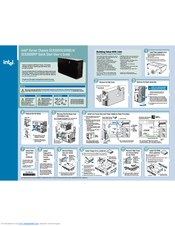
Intel SC5300BRP Quick Start Manual (1 page)
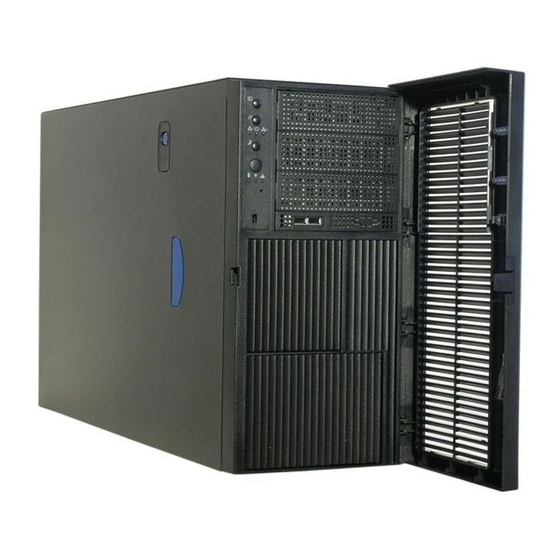
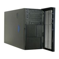
Server Chassis
Brand:
Intel
| Category:
Chassis
| Size: 6 MB
Advertisement
Related Products
Intel SC5300BD2 - Server Platform - 0 MB RAM
Intel SC5300
Intel SC5299BRPNA
Intel SC5299BRP
Intel SC5400BRP
Intel SC5400LX
Intel SC5400BRPNA - SC5400 Brp Chassis
Intel SC5299-E DP
Intel SC5299-E WS
Intel SC5275-E DP
Intel Categories
Motherboard
Computer Hardware
Server
Desktop
Server Board
More Intel Manuals
Login
Sign In
OR
Sign in with Facebook
Sign in with Google
Upload manual
Upload from disk
Upload from URL