Sign In
Upload
Manuals
Brands
IEI Technology Manuals
Desktop
IDS-310-AL
IEI Technology IDS-310-AL Digital Signage Manuals
Manuals and User Guides for IEI Technology IDS-310-AL Digital Signage. We have
1
IEI Technology IDS-310-AL Digital Signage manual available for free PDF download: User Manual
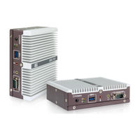
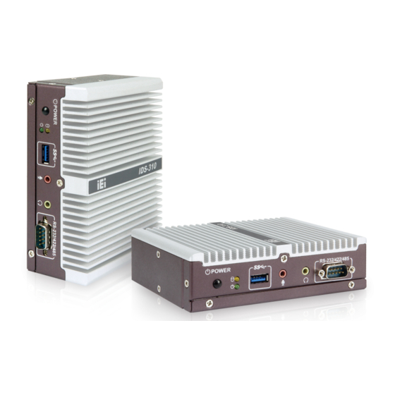
IEI Technology IDS-310-AL User Manual (114 pages)
Embedded System with Intel Celeron N3350E/J3455E, Three HDMI, Dual GbE LAN, RS-232/422/485, SATA 6Gb/s, Audio Jacks, USB 3.2 Gen 1, RoHS Compliant
Brand:
IEI Technology
| Category:
Desktop
| Size: 4 MB
Table of Contents
Table of Contents
7
1 Introduction
15
Overview
16
Figure 1-1: IDS-310-AL Series Embedded System
16
Features
17
Model Variations
17
Table 1-1: IDS-310-AL Model Variations
17
I/O Panels
18
Figure 1-2: I/O Panel - Front
18
Figure 1-3: I/O Panel - Rear
18
Bottom Panel
19
Technical Specifications
19
Figure 1-4: Bottom Panel
19
Table 1-2: Technical Specifications
20
Dimensions
21
IDS-310-AL-N1 Dimensions
21
Figure 1-5: IDS-310-AL-N1 Dimensions (MM)
21
IDS-310-AL-J1 Dimensions
22
Figure 1-6: IDS-310-AL-J1 Dimensions (MM)
22
2 Unpacking
23
Unpacking
24
Packing List
24
Optional Items
25
Table 2-1: Package List
25
Table 2-2: Optional Items
25
3 Installation
26
Anti-Static Precautions
27
Installation Precautions
27
High Surface Temperature
28
Bottom Surface Removal
29
Figure 3-1: Bottom Surface Retention Screws
29
Figure 3-2: Bottom Surface Removal
29
Bottom Surface Re-Installation
30
Wireless LAN Module Installation (Optional)
30
Figure 3-3: Bottom Surface Installation
30
Figure 3-4: Knockouts for Wireless Antenna
30
Figure 3-5: M.2 A-Key Slot Location
31
Figure 3-6: Inserting the WLAN Module
31
Figure 3-7: Securing the WLAN Module
32
Figure 3-8: Connecting RF Cables
32
Pcie Mini Module Installation
33
Figure 3-9: Securing SMA Connector and External Antenna Installation
33
Figure 3-10: Pcie Mini Slot Location
33
Figure 3-11: Removing the Retention Screws
34
Figure 3-12: Inserting the Pcie Mini Module into the Slot at an Angle
34
At/Atx Power Mode Selection
35
Figure 3-13: Securing the Pcie Mini Module
35
Figure 3-14: AT/ATX Switch Location
35
Mounting the System
36
Figure 3-15: Attach Mounting Bracket
36
Figure 3-16: Hook Onto Mounting Bracket
37
External Peripheral Interface Connection
38
Figure 3-17: External Peripheral Interface Connectors
38
LAN Connectors
39
Figure 3-18: RJ-45 Ethernet Connector
39
Table 3-1: LAN Connector Pinouts
39
Table 3-2:: Ethernet Connector Leds
39
HDMI Connectors
40
Table 3-3: HDMI Connector Pinouts
40
Power Connector
41
Figure 3-19: HDMI Connector
41
Figure 3-20: Power Connector
41
Table 3-4: Power Connector Pinouts
41
RS-232/422/485 Serial Port Connector
42
Table 3-5: RS-232/422/485 Serial Port Pinouts
42
USB 3.2 Gen 1 (5Gb/S) Connectors
43
Power -O N Procedure
43
Installation Checklist
43
Table 3-6: USB 3.2 Gen 1 Port Pinouts
43
Power-On Procedure
44
Reset the System
44
Figure 3-21: Power Button and Power LED
44
Figure 3-22: Reset Button Location
44
Flash Descriptor Security Override
45
Figure 3-23: Flash Descriptor Security Override Jumper Location
45
Table 3-7: Flash Descriptor Security Override Jumper Settings
45
Clear Cmos
46
Figure 3-24: Clear CMOS Jumper Location
46
Table 3-8: Clear CMOS Jumper Settings
46
4 Bios
47
Introduction
48
Starting Setup
48
Using Setup
48
BIOS Menu Bar
49
Getting Help
49
Table 4-1: BIOS Navigation Keys
49
Main
50
System Date [XX/XX/XX]
50
System Time [XX:XX:XX]
50
Advanced
51
ACPI Settings
52
ACPI Sleep State [S3 (Suspend to RAM)]
52
F81803 Super IO Configuration
53
Serial Port 1 Configuration
53
Serial Port [Enabled]
53
Transfer Mode [RS232]
53
Iwdd H/W Monitor
55
PC Health Status
55
USB Configuration
56
USB Devices
56
Legacy USB Support [Enabled]
56
CPU Configuration
57
EIST [Enabled]
57
C-States [Enabled]
58
Intel ® Virtualization Technology [Disabled]
58
VT-D [Disabled]
58
RTC Wake Settings
59
Wake System with Fixed Time [Disabled]
59
Power Saving Configuration
60
Power Saving Function(ERP) [Disabled]
60
Serial Port Console Redirection
61
Console Redirection [Disabled]
61
Console Redirection Settings
62
Terminal Type [ANSI]
62
Bits Per Second [115200]
62
Data Bits [8]
62
Parity [None]
62
Stop Bits [1]
62
Legacy Console Redirection Settings
64
Legacy Serial Redirection Port [COM1]
64
IEI Feature
65
Auto Recovery Function [Disabled]
65
Chipset
66
Intel IGD Configuration
67
North Bridge Configuration
67
Primary Display [IGD]
67
DVMT Pre-Allocated [256MB]
67
DVMT Total Gfx Mem [MAX]
67
LCD Control
69
Primary IGFX Boot Display [Auto]
69
HD-Audio Configuration
70
South Bridge Configuration
70
HD-Audio Support [Enable]
70
PCI Express Configuration
71
Onboard LAN1/LAN2 [Enable]
72
M2_KEYA1 [Enable]
73
Pcie Speed [Auto]
73
MPCIE1 [Enable]
74
Pcie Speed [Auto]
74
SATA Configuration
75
SATA Controller [Enable]
75
SATA Mode Selection [AHCI]
75
Hot Plug [Disabled]
75
Security
76
Administrator Password
76
User Password
76
Boot
77
Bootup Numlock State [On]
77
Quiet Boot [Enabled]
78
Launch PXE Oprom [Disabled]
78
Option ROM Messages [Force BIOS]
78
UEFI Boot [Disabled]
78
Boot Option Priority
78
Save & Exit
79
Save Changes and Reset
79
Discard Changes and Reset
79
Restore Defaults
79
Save as User Defaults
79
Restore User Defaults
79
5 Maintenance
81
System Maintenance Overview
82
Component Replacement Procedure
82
SO-DIMM Replacement
83
Figure 5-1: SO-DIMM Location
83
6 Interface Connectors
85
Peripheral Interface Connectors
86
Internal Peripheral Connectors
87
Battery Connector (BT1)
87
Table 6-1: Peripheral Interface Connectors
87
Table 6-2: Battery Connector (BT1) Pinouts
87
A-Key Slot (M2_KEYA1)
88
Digital I/O Connector (DIO1)
88
Firmware Programming Connector for CH7525 (CN1)
88
Table 6-3: Digital I/O Connector (DIO1) Pinouts
88
Table 6-4: Firmware Programming Connector for CH7525 (CN1) Pinouts
88
Table 6-5: M.2 A-Key Slot (M2_KEYA1) Pinouts
89
Pcie Mini Slot (MPCIE1)
90
Table 6-6: Pcie Mini Slot (MPCIE1) Pinouts
90
SATA Connector (SATA1)
91
SATA Power Connector (SATA_PWR1)
91
Smbus Connector (J_SMB2)
91
Table 6-7: SATA Connector (SATA1) Pinouts
91
Table 6-8: SATA Power Connector (SATA_PWR1) Pinouts
91
Table 6-9: Smbus Connector (J_SMB2) Pinouts
91
SPI Flash Connector, BIOS (J_SPI1)
92
SPI Flash Connector, EC (EC_JP1)
92
External Interface
92
Table 6-10: SPI Flash Connector (J_SPI1) Pinouts
92
Table 6-11: SPI Flash Connector (EC_JP1) Pinouts
92
Table 6-12: External Interface Panel Connectors
92
A Regulatory Compliance
93
B Safety Precautions
98
Safety Precautions
99
General Safety Precautions
99
Anti-Static Precautions
100
Product Disposal
101
Maintenance and Cleaning Precautions
102
Cleaning Tools
102
Maintenance and Cleaning
102
CBIOS Menu Options
104
Ids-310-Al Embedded System C.1 BIOS Configuration Options
105
Bios Configuration Options
105
D Watchdog Timer
107
E Error Beep Code
110
Pei Beep Codes
111
Dxe Beep Codes
111
F Hazardous Materials Disclosure
112
Rohs II Directive (2015/863/EU)
113
China Rohs
114
Advertisement
Advertisement
Related Products
IEI Technology IDS-310AI
IEI Technology IDS-310AI-AL-J1/8GB-R10
IEI Technology IBX-700 Series
IEI Technology IOVU-07F-AD
IEI Technology IOPS-Q67/H61
IEI Technology IVS-300
IEI Technology IVS-200-ULT2
IEI Technology ITCS-100-H81
IEI Technology ITG-100AI
IEI Technology IDS-330-ADL-P Series
IEI Technology Categories
Motherboard
Touch Panel
Computer Hardware
Single board computers
Desktop
More IEI Technology Manuals
Login
Sign In
OR
Sign in with Facebook
Sign in with Google
Upload manual
Upload from disk
Upload from URL