Sign In
Upload
Manuals
Brands
IEI Technology Manuals
Desktop
IVS-200-ULT2
IEI Technology IVS-200-ULT2 Manuals
Manuals and User Guides for IEI Technology IVS-200-ULT2. We have
1
IEI Technology IVS-200-ULT2 manual available for free PDF download: User Manual
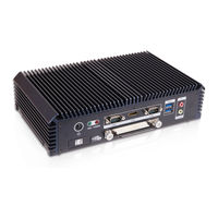
IEI Technology IVS-200-ULT2 User Manual (116 pages)
Fanless embedded system with Intel core i5-5350U/Celeron 3755U processor, quad GbE LAN, HDMI, Dual RS-232/422/485, USB 3.0, RoHS compliant
Brand:
IEI Technology
| Category:
Desktop
| Size: 6.13 MB
Table of Contents
Table of Contents
5
User Manual
1
Manual Conventions
4
1 Introduction
13
Overview
14
Benefits
14
Figure 1-1: IVS-200-ULT2 Series Embedded System
14
Features
15
Model Variations
15
Table 1-1: Model Variations
15
External Overview
16
Front Panel
16
Figure 1-2: Front Panel
16
Figure 1-3: Rear Panel
17
Rear Panel
17
Bottom Surface
18
Figure 1-4: Bottom Surface
18
Technical Specifications
19
Table 1-2: Technical Specifications
20
Dimensions
21
Figure 1-5: Dimensions (MM)
21
2 Unpacking
22
Unpacking
23
Packing List
23
Optional Items
24
Table 2-1: Package List
24
Table 2-2: Optional Items
25
3 Installation
26
Anti-Static Precautions
27
Installation Precautions
27
High Surface Temperature
28
Installation Procedure
29
Opening Bottom Cover
29
Figure 3-1: Bottom Cover Retention Screws
30
Figure 3-2: Opening Bottom Cover
30
Configure the Jumper Settings
31
Clear CMOS
31
Figure 3-3: Clear CMOS Button
31
ACC Mode On/Off
32
AT/ATX Mode Selection
32
Figure 3-4: AT/ATX Mode Select Switch Location
32
Figure 3-5: ACC Mode On/Off Switch Location
32
Figure 3-6: SSD Bracket Retention Screws
33
Figure 3-7: Removing SSD Bracket
33
Solid-State Drive Installation
33
Figure 3-8: SSD Retention Screws
34
Figure 3-9: SSD Installation
34
Figure 3-10: Pcie Mini Slot Location
35
Msata/Full-Size Pcie Mini Card Installation
35
Figure 3-11: Removing the Screw and Standoff for Half-Size Pcie Mini Card
36
Figure 3-12: Removing the Retention Screw
36
Figure 3-13: Inserting the Full-Size Pcie Mini Card into the Slot at an Angle
37
Figure 3-14: Securing the Full-Size Pcie Mini Card
37
Figure 3-15: Knockout Holes for External Antenna
38
Figure 3-16: Pcie Mini Slot Location
38
Odule I Nstallation (O Ptional )
38
WLAN/WWAN Module Installation (Optional)
38
Figure 3-17: Removing the Retention Screw
39
Figure 3-18: Inserting the WLAN/WWAN Module
39
Figure 3-19: Securing WLAN/WWAN Module and Connecting RF Cable
40
Figure 3-20: Securing SMA Connector and External Antenna Installation
40
Figure 3-21: Unlock Slot Cover
41
Nstallation (O Ptional )
41
SIM Card Installation (Optional)
41
Table 3-1: COM1 and COM2 Pinouts
42
Mounting the System
43
Mounting with Mounting Brackets
43
Figure 3-22: SIM Card Installation
42
Rs-232/422/485 Serial Port Connection
42
Figure 3-23: Removing Foot Pads
43
Figure 3-24: Mounting Bracket Retention Screws
44
Mounting with VESA Mount Kit (Optional)
44
Figure 3-25: Wall-Mounting Bracket
45
Figure 3-27: Tighten Retention Screw
46
Power -O N Procedure
47
Installation Checklist
47
Terminal Block Pinouts
47
Figure 3-26: Mount the Embedded System
46
Figure 3-28: Terminal Block Pinouts
47
Driver Installation
48
Figure 3-29: Power Button and Power LED
48
Power-On Procedure
48
4 Bios
50
Introduction
51
Starting Setup
51
Using Setup
51
BIOS Menu Bar
52
Getting Help
52
Unable to Reboot after Configuration Changes
52
Table 4-1: BIOS Navigation Keys
52
Main
53
BIOS Menu 1: Main
54
System Date [XX/XX/XX]
54
System Time [XX:XX:XX]
54
Advanced
55
BIOS Menu 2: Advanced
55
CPU Configuration
56
BIOS Menu 3: CPU Configuration
56
Hyper-Threading [Enabled]
57
Active Processor Cores [All]
57
Intel Virtualization Technology [Enabled]
58
EIST [Enabled]
58
Intel TXT(LT) Support [Disabled]
58
ACPI Settings
59
BIOS Menu 4: ACPI Settings
59
ACPI Sleep State [S1 (CPU Stop Clock)]
59
F81866 Super IO Configuration
60
Serial Port N Configuration
60
BIOS Menu 5: F81866 Super IO Configuration
60
BIOS Menu 6: Serial Port N Configuration Menu
60
Serial Port [Enabled]
61
Change Settings [Auto]
61
Serial Port Mode [RS232]
62
Serial Port [Enabled]
62
Change Settings [Auto]
62
Serial Port Mode [RS232]
63
RTC Wake Settings
64
BIOS Menu 7: RTC Wake Settings
64
Wake System with Fixed Time [Disabled]
64
Serial Port Console Redirection
65
BIOS Menu 8: Serial Port Console Redirection
65
Console Redirection [Disabled]
65
Console Redirection Settings
66
BIOS Menu 9: Console Redirection Settings
66
Terminal Type [ANSI]
66
Bits Per Second [115200]
66
Data Bits [8]
67
Parity [None]
67
Stop Bits [1]
67
Iei Feature
68
BIOS Menu 10: Iei Feature
68
Auto Recovery Function [Disabled]
68
SATA Configuration
69
BIOS Menu 11: SATA Configuration
69
SATA Controller(S) [Enabled]
69
SATA Mode Selection [AHCI]
69
Intel(R) Rapid Start Technology
70
BIOS Menu 12: Intel(R) Rapid Start Technology Configuration
70
Hot Plug [Disabled]
70
Intel(R) Rapid Start Technology [Disabled]
70
USB Configuration
71
BIOS Menu 13: USB Configuration
71
USB Devices
71
Legacy USB Support [Enabled]
71
Iwdd H/W Monitor
72
BIOS Menu 14: Iwdd H/W Monitor
72
PC Health Status
72
Chipset
73
BIOS Menu 15: Chipset
73
System Agent (SA) Configuration
74
BIOS Menu 16: System Agent (SA) Configuration
74
VT-D [Enabled]
74
Graphics Configuration
75
BIOS Menu 17: Graphics Configuration
75
Primary IGFX Boot Display [VBIOS Default]
75
DVMT Pre-Allocated [256M]
75
Memory Configuration
76
BIOS Menu 18: Memory Configuration
76
DVMT Total Gfx Mem [MAX]
76
PCH-IO Configuration
77
BIOS Menu 19: PCH-IO Configuration
77
Restore AC Power Loss [Last State]
77
Power Saving Function(EUP) [Disabled]
77
PCI Express Configuration
78
BIOS Menu 20: PCI Express Configuration
78
Pcie Speed [Auto]
78
Detect Non-Compliance Device [Disabled]
78
PCH Azalia Configuration
79
BIOS Menu 21: PCH Azalia Configuration
79
Azalia(Hd Audio) [Enabled]
79
Security
80
BIOS Menu 22: Security
80
Administrator Password
80
User Password
80
Boot
81
BIOS Menu 23: Boot
81
Bootup Numlock State [On]
81
Quiet Boot [Enabled]
82
Launch PXE Oprom [Disabled]
82
Option ROM Messages [Force BIOS]
82
UEFI Boot [Disabled]
82
Save & Exit
83
BIOS Menu 24: Save & Exit
83
Save Changes and Reset
83
Discard Changes and Reset
83
Restore Defaults
83
Save as User Defaults
83
Restore User Defaults
84
5 Troubleshooting and Maintenance
85
Ivs-200-Ult2 System Maintenance Overview
86
System Troubleshooting
86
The System Doesn't Turn on
86
More Troubleshooting
87
The System Doesn't Boot up
87
Component Replacement Procedure
88
SO-DIMM Replacement
88
Figure 5-1: SO-DIMM Location
89
Figure 5-2: SO-DIMM Installation
89
6 Interface Connectors
90
Peripheral Interface Connectors
91
Internal Peripheral Connectors
91
Figure 6-1: Jumper and Connector Locations
91
Battery Connector (CN1)
92
Digital I/O Connector (DIO1)
92
Table 6-1: Peripheral Interface Connectors
92
Table 6-2: Battery Connector (CN1) Pinouts
92
Table 6-3: Digital I/O Connector (DIO1) Pinouts
92
Fan Connector (FAN1)
93
Serial Port Connectors (COM3 ~ COM6)
93
SATA Power Connector (SATA_PWR1)
93
Table 6-4: Fan Connector (FAN1) Pinouts
93
Table 6-5: RS-232 Serial Port Connector (COM3 ~ COM6) Pinouts
93
Table 6-6: SATA Power Connector (SATA_PWR1) Pinouts
93
SPI Flash Connector, BIOS (SPI1)
94
SPI Flash Connector, EC (JSPI1)
94
External Interface Panel Connectors
94
Ethernet Connector (LAN1)
94
Table 6-7: SPI Flash Connector (SPI1) Pinouts
94
Table 6-8: SPI Flash Connector (JSPI1) Pinouts
94
Table 6-9: Ethernet Connector (LAN1) Pinouts
94
Ethernet Connectors (LAN2 ~ LAN4)
95
RS-232/422/485 DB-9 Serial Ports (COM1, COM2)
95
Table 6-10: Ethernet Connectors (LAN2 ~ LAN4) Pinouts
95
Table 6-11: RS-232/422/485 DB-9 Serial Port (COM1, COM2) Pinouts
95
Table 6-12: USB 2.0 Connectors (USB_CON2) Pinouts
95
USB 2.0 Connectors (USB_CON2)
95
Power Input Terminal Block (DC_IN1)
96
Table 6-13: USB 3.0 Connectors (USB_CON1) Pinouts
96
Table 6-14: Power Input Terminal Block (DC_IN1) Pinouts
96
Table 6-15: VGA Connector (VGA1) Pinouts
96
USB 3.0 Connectors (USB_CON1)
96
VGA Connector (VGA1)
96
A Regulatory Compliance
97
B Safety Precautions
102
Safety Precautions
103
B.1 S Afety P Recautions
103
General Safety Precautions
103
Anti-Static Precautions
104
Product Disposal
105
Maintenance and Cleaning Precautions
106
Cleaning Tools
106
Maintenance and Cleaning
106
CBIOS Menu Options
108
C.1 BIOS Configuration Options
109
Bios Configuration Options
109
D Watchdog Timer
111
Example Program
113
E Hazardous Materials Disclosure
114
Advertisement
Advertisement
Related Products
IEI Technology IBX-700 Series
IEI Technology IOVU-07F-AD
IEI Technology IOPS-Q67/H61
IEI Technology IVS-300
IEI Technology ITCS-100-H81
IEI Technology ITG-100AI
IEI Technology IDS-310-AL
IEI Technology IDS-310AI
IEI Technology IDS-310AI-AL-J1/8GB-R10
IEI Technology IVS-100-BT
IEI Technology Categories
Motherboard
Touch Panel
Computer Hardware
Single board computers
Desktop
More IEI Technology Manuals
Login
Sign In
OR
Sign in with Facebook
Sign in with Google
Upload manual
Upload from disk
Upload from URL