Sign In
Upload
Manuals
Brands
IEI Technology Manuals
Motherboard
gKINO-DMF-216-R10
IEI Technology gKINO-DMF-216-R10 Manuals
Manuals and User Guides for IEI Technology gKINO-DMF-216-R10. We have
2
IEI Technology gKINO-DMF-216-R10 manuals available for free PDF download: User Manual, Quick Installation Manual
IEI Technology gKINO-DMF-216-R10 User Manual (134 pages)
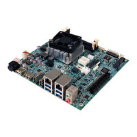
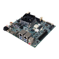
gKINO-DMF series. Mini-ITX SBC supports AMD RX-421BD/216GD on board SoC (quad-core 2.1GHz, 35W), DDR4, triple independent displays, HDMI/DP, dual GbE, SATA 6Gb/s, USB 3.0, PCIe mini, M.2, HD audio and RoHS
Brand:
IEI Technology
| Category:
Motherboard
| Size: 5.73 MB
Table of Contents
User Manual
1
Table of Contents
5
Figure 1-1: Gkino-DMF
13
1 Introduction
15
Introduction
16
Features
17
Model Variations
17
Table 1-1: Gkino-DMF Model Variations
17
Connectors
18
Figure 1-2: Connectors (Front Side)
18
Figure 1-3: Connectors (Solder Side)
19
Figure 1-4: Dimensions (MM)
20
Figure 1-5: Data Flow Diagram
21
Technical Specifications
22
Data Flow
21
Dimensions
20
Table 1-2: Technical Specifications
24
2 Unpacking
25
Anti-Static Precautions
26
Unpacking Precautions
26
Packing List
27
Optional Items
28
3 Connectors
29
Figure 3-1: Connector and Jumper Locations (Front)
30
Table 3-2: Rear Panel Connectors
33
Table 3-1: Peripheral Interface Connectors
33
Figure 3-2: DC-IN Power Connector Location
34
Table 3-3: DC-IN Power Connector Pinouts
34
Audio Connector
35
Figure 3-3: Audio Connector Location
35
Table 3-4: Audio Connector Pinouts
35
Battery Connector
36
Figure 3-4: Battery Connector Location
36
Table 3-5: Battery Connector Pinouts
36
Cctalk Connectors
37
Figure 3-5: Cctalk Connector Locations
37
Table 3-6: Cctalk Connector Pinouts
37
Chassis Intrusion Connector
38
Figure 3-6: Chassis Intrusion Connector Location
38
Table 3-7: Chassis Intrusion Connector Pinouts
38
Digital I/O Connector
39
Table 3-8: Digital I/O Connector Pinouts
39
Fan Connectors
40
Internal Peripheral Connectors
34
DC-IN Power Connector
34
Peripheral Interface Connectors
30
Gkino-DMF Layout
30
Figure 3-1: Connector and Jumper Locations (Rear)
31
Peripheral Interface Connectors
32
External Interface Panel Connectors
33
Figure 3-7: Digital I/O Connector Location
39
Figure 3-8: Fan Connector Locations
40
Table 3-9: Fan Connector Pinouts
40
Figure 3-14: Pcie Mini Card Slot Location
46
Figure 3-27: Displayport++ Connector Pinout Locations
59
Table 3-23: Displayport++ Connector Pinouts
59
Table 3-24: HDMI Connector Pinouts
59
LAN and USB 3.0 Combo Connectors
60
Figure 3-15: Pcie X1 Slot Location
47
Pcie X8 Card Slot
47
Table 3-13: Pcie Mini Card Slot Pinouts
47
Figure 3-16: RS-232 Serial Port Connector Locations
48
Serial Port Connectors
48
Table 3-14: RS-232 Serial Port Connector Pinouts
48
Figure 3-17: RS-232/422/485 Connector Locations
49
RS-232/422/485 Serial Port Connectors
49
Table 3-15: RS-232/422/485 Connector Pinouts
49
Figure 3-18: SATA 6Gb/S Drive Connectors Locations
50
SATA 6Gb/S Drive Connectors
50
Table 3-16: DB-9 RS-422/485 Pinouts
50
Figure 3-19: SATA Power Connector Locations
51
SATA Power Connectors
51
Table 3-17: SATA Power Connector Pinouts
51
Figure 3-20: Smbus Connector Location
52
Smbus Connector
52
Table 3-18: Smbus Connector Pinouts
52
Figure 3-21: SPI Flash Connector Location
53
Figure 3-22: SPI Flash Connector Location
53
SPI Flash Connector, BIOS
53
Table 3-19: SPI Flash Connector Pinouts
53
SPI Flash Connector, EC
54
Table 3-20: SPI Flash Connector Pinouts
54
Figure 3-23: TPM Connector Location
55
Table 3-21: TPM Connector Pinouts
55
TPM Connector
55
Figure 3-24: USB Connector Locations
56
Table 3-22: USB Connector Pinouts
56
USB 2.0 Connectors
56
Audio Jacks
57
External Peripheral Interface Connector Panel
57
Figure 3-25: External Peripheral Interface Connector
57
Displayport++ Connector
58
Figure 3-26: Audio Connector
58
HDMI Connectors
59
Figure 3-29: Ethernet Connector
60
Figure 3-28: HDMI Connector
60
Table 3-25: LAN1 Ethernet Connector Pinouts
60
Table 3-27: USB 3.0 Port Pinouts
61
Table 3-26: Connector Leds
61
Power Connector
62
USB 2.0 Connector
62
Figure 3-9: Front Panel Connector Location
41
Front Panel Connector
41
Table 3-10: Front Panel Connector Pinouts
41
Figure 3-10: I 2 C Connector Location
42
I 2 C Connector
42
Table 3-11: I 2 C Connector Pinouts
42
Figure 3-11: LAN LED Connector Locations
43
LAN LED Connectors
43
Table 3-12: LAN LED Connector Pinouts
43
Figure 3-12: M.2 Slot Location
44
Slot
44
Figure 3-13: Microsd Card Slot Location
45
Microsd Slot
45
Pcie Mini Card Slot
45
Figure 3-30: Power Connector
62
Table 3-28: USB 2.0 Port Pinouts
62
4 Installation
63
Anti-Static Precautions
64
Installation Considerations
64
Figure 4-1: SO-DIMM Installation (DDR4)
66
So-DIMM Installation
66
Module Installation
67
Pcie Mini Card Installation
67
Full-Size Pcie Mini Card Installation
67
M.2 M Odule I Nstallation
67
Figure 4-3: Inserting the Full-Size Pcie Mini Card into the Slot at an Angle
68
Figure 4-2: Removing the Retention Screw
68
Figure 4-4: Securing the Full-Size Pcie Mini Card
69
Half-Size Pcie Mini Card Installation
69
Figure 4-6: Installing the Standoff
70
Figure 4-7: Inserting the Half-Size Pcie Mini Card into the Slot at an Angle
71
Figure 4-8: Securing the Half-Size Pcie Mini Card
71
Figure 4-9: AT/ATX Mode Select Switch Location
72
Table 4-1: AT/ATX Mode Select Switch Settings
72
Figure 4-10: Clear CMOS Button Location
73
Airflow
74
Chassis Installation
74
Figure 4-11: M.2 and SATA2 Select Switch Location
74
Motherboard Installation
74
Figure 4-12: SATA Drive Cable Connection
75
Sata Drive Connection
75
And SATA2 Select Jumper
73
Clear CMOS Button
73
Figure 4-5: Removing Retention Screw and Standoff
70
System Configuration
72
AT/ATX Mode Select Switch
72
Figure 4-13: SATA Power Drive Connection
76
5 Bios
77
Introduction
78
Starting Setup
78
Using Setup
78
Getting Help
79
Unable to Reboot after Configuration Changes
79
BIOS Menu Bar
79
Main
80
Advanced
81
Trusted Computing
82
ACPI Settings
83
IDE Configuration
84
F81866 Super IO Configuration
85
Serial Port N Configuration
85
Serial Port 1 Configuration
86
Serial Port 2 Configuration
87
Serial Port 3 Configuration
88
Serial Port 4 Configuration
89
Serial Port 5 Configuration
90
Serial Port 6 Configuration
91
Iwdd H/W Monitor
93
Smart Fan Mode Configuration
94
RTC Wake Settings
96
Power Saving Configuration
97
CPU Configuration
99
Node 0 Information
100
Nvme Configuration
100
USB Configuration
101
Chipset
102
South Bridge
103
SB SATA Configuration
104
GFX Configuration
105
North Bridge
106
Security
107
Boot
108
Save & Exit
110
6 Software Drivers
112
Figure 6-1: Available Drivers
113
Software Installation
113
Available Software Drivers
114
A Regulatory Compliance
115
B Product Disposal
117
C Bios Menu Options
119
D Terminology
122
E Digital I/O Interface
126
F Watchdog Timer
129
G Hazardous Materials Disclosure
132
Advertisement
IEI Technology gKINO-DMF-216-R10 Quick Installation Manual (14 pages)
Mini-ITX SBC
Brand:
IEI Technology
| Category:
Single board computers
| Size: 0.2 MB
Advertisement
Related Products
IEI Technology gKINO-DMF-421-R10
IEI Technology gKINO-DMF Series
IEI Technology gKINO-V1000 Series
IEI Technology gKINO-R1000 Series
IEI Technology gKINO-V1605B-R10
IEI Technology gKINO-V1202B-R10
IEI Technology gKINO-R1606G-R10
IEI Technology gKINO-R1505G-R10
IEI Technology gKINO-V1605B
IEI Technology gKINO-V1202B
IEI Technology Categories
Motherboard
Touch Panel
Computer Hardware
Single board computers
Desktop
More IEI Technology Manuals
Login
Sign In
OR
Sign in with Facebook
Sign in with Google
Upload manual
Upload from disk
Upload from URL