Sign In
Upload
Manuals
Brands
Hypertherm Manuals
Welding System
Powermax30 AIR
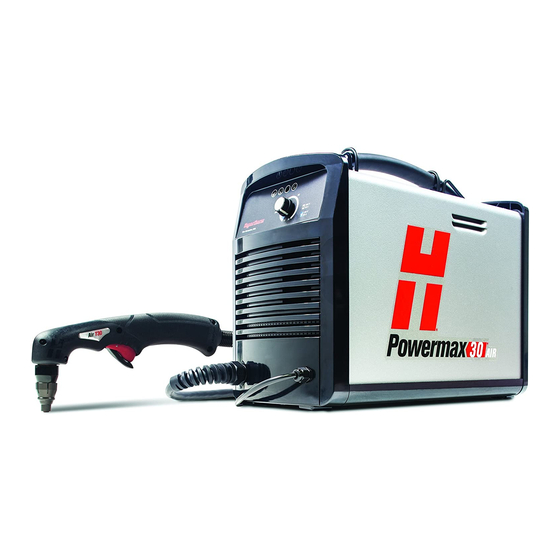
Hypertherm Powermax30 AIR Plasma Cutter Manuals
Manuals and User Guides for Hypertherm Powermax30 AIR Plasma Cutter. We have
11
Hypertherm Powermax30 AIR Plasma Cutter manuals available for free PDF download: Service Manual, Operator's Manual, Field Service Bulletin, Manual
Hypertherm Powermax30 AIR Service Manual (223 pages)
Plasma Arc Cutting System with Integrated Air Compressor
Brand:
Hypertherm
| Category:
Welding System
| Size: 12 MB
Table of Contents
Table of Contents
7
Electromagnetic Compatibility (EMC
13
Introduction
13
Installation and Use
13
Assessment of Area
13
Methods of Reducing Emissions
13
Mains Supply
13
Maintenance of Cutting Equipment
13
Cutting Cables
13
Earthing of the Workpiece
13
Equipotential Bonding
13
Screening and Shielding
14
Warranty
15
Attention
15
General
15
Patent Indemnity
15
Limitation of Liability
15
National and Local Codes
15
Liability Cap
15
Insurance
16
Transfer of Rights
16
1 Specifications
17
Safety Information
17
System Description
17
Power Supply Dimensions
18
System Weights
18
Hypertherm System Ratings
19
Torch Dimensions
20
Torch Weight
20
Cutting Specifications
21
IEC Symbols
22
Noise Levels
22
Symbols and Marks
23
2 Power Supply Setup
25
Unpack the Plasma System
25
Claims
25
System Contents
26
Position the Plasma Cutting System
27
Prepare the Electrical Power
27
Voltage Configurations
27
Requirements for Grounding
29
Power Cord Considerations
29
CSA Power Cords and Plugs
29
CE Power Cords
30
Install a Plug on the Power Cord
30
Extension Cord Recommendations
31
Generator Recommendations
31
3 Torch Setup
33
Introduction
33
Hand Torch Components
33
Consumable Life
34
Consumable Use
35
Using the Cut Charts
35
Consumable Set
36
240 V / 30 a Cutting
37
120 V / 20 a Cutting
39
Powermax30 AIR Service Manual
40
4 Operation
41
Controls and Indicators
41
Rear Controls
41
Front Panel Controls and Indicator LED Symbols
42
Operate the Plasma System
43
Step 1 - Install the Consumables
43
Step 2 - Connect the Electrical Power
44
Cutting Expanded Metal
45
Decrease Output Current for Lower-Rated Power Plugs
45
Operating the System on a 120 V / 20 a Circuit
45
Operating the System on a 240 V / 20 a Circuit
45
Step 3 - Adjust the Output Current
45
Step 4 - Attach the Ground Clamp
46
Step 5 - Power on the System
46
Step 6 - Check the Indicator Leds
47
Step 7 - Make Sure the System Is Ready, and Start Cutting
47
What to Expect During and after Cutting
47
Internal Compressor and Fan Activity
47
Postflow
47
Water under the Power Supply
47
Understand Duty-Cycle Limitations
48
System Operation Guidelines
49
Hand Torch Operation
50
Safety Catch Operation
50
Hand Torch Cutting Guidelines
51
Recommendations for Cutting at 120 V
51
Edge Start on a Workpiece
52
Pierce a Workpiece
53
Common Hand-Cutting Faults
54
Minimizing Dross
54
5 Troubleshooting and System Tests
55
Theory of Operation
55
Functional Description
55
Sequence of Operation
56
Troubleshooting Preparation
57
Test Equipment
58
Troubleshooting Procedures and Sequence
58
External Inspection
59
Internal Inspection
59
Initial Resistance Check
59
Check the Power Switch
60
Power Supply Overview
62
Troubleshooting Guide
63
Power LED Faults
63
Temperature LED Faults
65
Internal Compressor LED Faults
66
Torch Cap LED Faults
68
Common Cutting Issues
69
Control Board Leds
71
Use the Control Board Rest and Error Leds to Troubleshoot
72
Reset LED
72
Error LED
73
System Tests
73
Test 1 - Voltage Input
78
Test 2 - Power Board Voltage Checks
80
Test 3 - VBUS and Voltage Balance on Power Board
82
Test 4 - Solenoid Valve
84
Test 5 - Torch Stuck Open or Torch Stuck Closed
85
Test 6 - Plasma Start
87
Test 7 - Torch Cap-Sensor
89
Test 8 - Fan
90
Test 9 - Internal Compressor, Compressor-Driver Board, and Power Board
91
Test 9A - Check the Diagnostic LED (D5) on the Compressor-Driver Board
91
Test 9B - Check the Internal Compressor
92
Test 9C - Check the Compressor-Driver Board
93
Test 9D - Check the Power Board
95
Powermax30 AIR Service Manual
96
6 Power Supply Component Replacement
97
Replace the Power Supply Cover
98
Replace the Component Barrier
100
Detach and Reattach the Front Panel
102
Detach and Reattach the Rear Panel
104
Replace the Power Cord and Strain Relief
107
Replace the Power Switch
116
Replace the Control Board
118
Replace the Compressor-Driver Board
121
Replace the Power Board
126
Replace the Drain Hose, Gas Supply Hoses, and 90° Fitting
133
Replace the Wire Group
137
Replace the Solenoid Valve
142
Replace the Torch Lead and Strain Relief
144
Replace the Air Filter Assembly
148
Replace the Air Filter Bowl and Air Filter Element
151
Replace the Fan
155
Replace the Heat Exchange Coil
157
Replace the Internal Compressor
160
Replace the Air Inlet Filter in the Internal Compressor
165
Replace the Front Panel
166
Replace the Rear Panel
169
Replace the Base
173
Replace the Magnetics Assembly
175
Replace the Work Lead and Ground Clamp
180
7 Torch Component Replacement
185
Torch Components
186
Replace the Handle
187
Replace the Trigger Assembly
191
Replace the Torch Body
193
Replace the Start Switch
195
Replace the Cap-Sensor Switch
196
Replace the Torch Lead
197
8 Parts
201
Power Supply Parts
202
Exterior, Front
202
Exterior, Rear
203
Interior, Power Board Side
204
Interior, Control Board and Power Switch
205
Interior, Fan Assembly
206
Interior, Pneumatics (Fan Side)
207
Interior, Wires
208
Power Supply Base and Magnetics
209
Hand Torch Parts
210
Hand Torch Consumables
211
Accessory Parts
212
Safety-Critical Parts
213
Recommended Spare Parts
215
Power Supply Labels
216
Consumables Label
216
CSA Warning Label
217
CE Warning Label
218
9 Wiring Diagrams
219
Process Flow for Troubleshooting Internal Compressor and Temperature Fault Leds
220
Timing Chart for Torch Start
221
Powermax30 AIR Schematic
222
Powermax30 AIR Service Manual
223
Advertisement
Hypertherm Powermax30 AIR Service Manual (201 pages)
Plasma Arc Cutting System
Brand:
Hypertherm
| Category:
Welding System
| Size: 15 MB
Table of Contents
Table of Contents
7
Electromagnetic Compatibility (EMC
13
Assessment of Area
13
Installation and Use
13
Introduction
13
Methods of Reducing Emissions
13
Mains Supply
13
Cutting Cables
14
Earthing of the Workpiece
14
Equipotential Bonding
14
Maintenance of Cutting Equipment
14
Screening and Shielding
14
Attention
15
General
15
Warranty
15
Insurance
16
Liability Cap
16
Limitation of Liability
16
National and Local Codes
16
Patent Indemnity
16
Transfer of Rights
16
Specifications
17
Safety Information
17
System Description
17
Power Supply Dimensions
18
System Weights
18
Hypertherm System Ratings
19
Torch Dimensions
20
Torch Weight
20
Cutting Specifications
20
Symbols and Marks
21
IEC Symbols
22
Noise Levels
22
Power Supply Setup
23
Unpack the Powermax System
23
Claims
23
System Contents
24
Position the Plasma Cutting System
25
Prepare the Electrical Power
25
Voltage Configurations
25
Requirements for Grounding
26
Power Cord Considerations
26
CSA Power Cords and Plugs
26
CE and CCC Power Cords
27
Extension Cord Recommendations
28
Generator Recommendations
28
Prepare the Gas Supply
29
Connect the Gas Supply
29
Additional Gas Filtration
30
Torch Setup
31
Introduction
31
Hand Torch Components
31
Consumable Life
32
Choose the Consumables
32
Using the Cut Charts
33
General-Purpose Consumables
34
240 V / 30 a Cutting
35
Finecut Consumables
36
120 V / 25 a Cutting
37
120 V / 30 a Cutting
38
Powermax30 XP Service Manual 808150 Revision
38
Operation
39
Controls and Indicators
39
Rear Controls
39
Front Controls and Leds
40
Operate the Powermax30 XP
41
Connect the Electrical Power and Gas Supply
41
Install the Consumables
42
Adjust the Gas Pressure and Output Current
44
Attach the Ground Clamp
44
Power on the System
44
Check the Indicator Leds
46
Verify the System Is Ready
46
Understand Duty-Cycle Limitations
46
System Operation Guidelines
47
Hand Torch Operation
48
Safety Catch Operation
48
Hand Torch Cutting Guidelines
49
Edge Start on a Workpiece
50
Pierce a Workpiece
51
Gouge a Workpiece
52
Common Hand-Cutting Faults
54
Troubleshooting and System Tests
55
Theory of Operation
55
Functional Description
55
Sequence of Operation
56
Troubleshooting Preparation
57
Test Equipment
57
Troubleshooting Procedures and Sequence
57
External Inspection
59
Internal Inspection
59
Initial Resistance Check
59
Check the Power Switch
60
Power Supply Overview
62
Troubleshooting Guide
63
Control Board Leds
69
Use the Control Board Error and Reset Leds to Troubleshoot
70
System Tests
71
Test 1 - Voltage Input
74
Test 2 - Power Board Voltage Checks
76
Test 3 - VBUS and Voltage Balance
78
Test 4 - Solenoid Valve
80
Test 5 - Torch Stuck Open or Torch Stuck Closed
81
Test 6 - Plasma Start
82
Test 7 - Torch Cap-Sensor
84
Test 8 - Fan
85
Test 9 - Pressure Switch
86
Power Supply Component Replacement
87
Disconnect the Power and Gas Supply
87
Replacing the Power Supply Cover
88
Replacing the Component Barrier
90
Detaching and Reattaching the Front Panel
92
Table of Contents
93
Detaching and Reattaching the Rear Panel
95
Figure 32
95
Place Another Screwdriver or Similar Object into the Opening between the Panel and the Base to Keep the First Corner
96
Figure 33
96
Repeat Step 5 and Step 6 on the Other Corner of the Panel
96
10. Gently Pull the Panel Away from the Power Supply
96
Replacing the Power Cord and Strain Relief
98
Replacing the Power Switch
105
Replacing the Control Board
107
Replacing the Power Board
109
Replacing the Fan
116
Table of Contents
118
Replacing the Drain Hose, Gas Supply Hoses, and 90° Fitting
119
Figure 57
121
Solenoid Valve
121
Replacing the Wire Group
123
Reconnect the Gas Supply and Power Cord, and Set the Power Switch to on (I)
124
Replacing the Solenoid Valve
130
Replacing the Torch Lead and Strain Relief
133
Replacing the Pressure Switch
139
Replacing the Air Filter/Regulator and Pressure Switch Assembly
141
Replacing the Air Inlet Fittings
146
Replacing the Air Filter Bowl and Air Filter Element
148
Replacing the Front Panel
152
Replacing the Rear Panel
156
Replacing the Base
160
Replacing the Magnetics Assembly
162
Replacing the Work Lead and Ground Clamp
167
See Install the Power Supply Cover
124
Torch Component Replacement
171
Disconnect the Power, Gas Supply, and Torch
172
Replacing the Handle
173
Replacing the Trigger Assembly
177
Replacing the Torch Body
178
Replacing the Start Switch
180
Replacing the Cap-Sensor Switch
181
Replacing the Torch Lead
182
Parts
185
Power Supply Parts
186
Exterior, Front
186
Exterior, Rear
187
Interior, Power Board Side
188
Control Board and Power Switch
189
Interior, Fan Side
190
Power Supply Base and Magnetics
192
Duramax LT Hand Torch Parts
193
Duramax LT Hand Torch Consumables
194
Accessory Parts
195
Safety-Critical Parts
196
Recommended Spare Parts
197
Powermax30 XP Labels
198
Wiring Diagrams
199
Powermax Generic Timing Chart
200
Powermax30 XP Schematic
201
Hypertherm Powermax30 AIR Operator's Manual (98 pages)
Plasma arc cutting system
Brand:
Hypertherm
| Category:
Welding System
| Size: 5 MB
Table of Contents
Warranty
7
Table of Contents
9
Safety
13
Recognize Safety Information
14
Follow Safety Instructions
14
Cutting Can Cause Fire or Explosion
14
Electric Shock Can Kill
15
Static Electricity Can Damage Circuit Boards
15
Toxic Fumes Can Cause Injury or Death
16
A Plasma Arc Can Cause Injury and Burns
17
Arc Rays Can Burn Eyes and Skin
17
Grounding Safety
18
Compressed Gas Equipment Safety
18
Gas Cylinders Can Explode if Damaged
18
Noise Can Damage Hearing
19
Pacemaker and Hearing Aid Operation
19
A Plasma Arc Can Damage Frozen Pipes
19
Additional Safety Information
19
Symbols and Markings
20
Warning Labels
21
Dry Dust Collection Information
23
Section 1A
25
Sécurité
25
Identifier Les Consignes De Sécurité
26
Suivre Les Instructions De Sécurité
26
Le Coupage Peut Provoquer Un Incendie Ou Une Explosion
26
Les Chocs Électriques Peuvent Être Fatals
27
L'électricité Statique Peut Endommager Les Cartes De Circuits Imprimés
27
Les Vapeurs Toxiques Peuvent Provoquer Des Blessures Ou La Mort
28
L'arc Plasma Peut Provoquer Des Blessures Ou Des Brûlures
29
Les Rayons De L'arc Peuvent Brûler Les Yeux Et La Peau
29
Mise À La Masse Et À La Terre
30
Sécurité Des Bouteilles De Gaz Comprimé
30
Les Bouteilles De Gaz Comprimé Peuvent Exploser En Cas De Dommages
30
Le Bruit Peut Provoquer Des Problèmes Auditifs
31
Pacemakers Et Prothèses Auditives
31
Un Arc Plasma Peut Endommager Les Tuyaux Gelés
31
Symboles Et Marquage
32
Étiquette De Sécurité
33
Étiquettes De Sécurité
34
Information Sur Le Dépoussiérage
35
Seguridad
37
Reconocimiento De Información De Seguridad
38
Siga Las Instrucciones De Seguridad
38
Los Cortes Pueden Provocar Incendios O Explosiones
38
El Choque Eléctrico Puede Provocar La Muerte
39
Electricidad Estática Puede Dañar Tablillas De Circuito
39
Humos Tóxicos Pueden Causar Lesiones O Muerte
40
El Arco De Plasma Puede Causar Lesiones Y Quemaduras
41
Los Rayos Del Arco Pueden Producir Quemaduras En Los Ojos Y En La Piel
41
Seguridad De Toma a Tierra
42
Seguridad De Los Equipos De Gas Comprimido
42
Los Cilindros De Gas Pueden Explotar Si Están Dañados
42
El Ruido Puede Deteriorar La Audición
43
Operación De Marcapasos Y De Audífonos
43
Un Arco Plasma Puede Dañar Tubos Congelados
43
Símbolos Y Marcas
44
Etiquetas De Advertencia
45
Información Sobre La Colección De Polvo Seco
47
Specifications
49
System Description
50
Power Supply Dimensions and Weight
50
Power Supply Ratings
51
Torch Dimensions
52
T30V Torch Ratings
52
Symbols and Markings
53
Mark
53
CE Mark
53
IEC Symbols
53
Setup
55
Unpack the Powermax30
56
Claims
56
Contents
56
Position the Power Supply
57
Voltage Configurations
57
Requirements for Grounding
57
Power Cord Considerations
58
Power Cord and Plugs for CSA Power Supplies
58
Power Cord for CE Power Supplies
59
Extension Cord Recommendations
60
Generator Recommendations
60
Gas Supply
61
Connection
61
Additional Gas Filtration
62
Operation
63
Controls and Indicators
64
Front Controls and Leds
64
Rear Controls
64
Install the Consumables
65
Attach the Work Clamp
66
Power on the System
66
Hand Torch Operation
68
Safety Trigger Operation
68
Hand Torch Cutting Hints
69
To Start a Cut from the Edge of the Workpiece
70
To Pierce a Workpiece
71
Cut Chart
72
Duty Cycle and Overheating
73
Common Cutting Faults
73
Routine Maintenance
76
Inspect the Consumables
77
Basic Troubleshooting
78
Repairs
81
Remove and Replace the Cover and Nomex® Barrier
81
Remove an Endcap
83
Disconnect the Torch Lead
85
Replace the Work Lead
87
Replace the Power Cord (CSA)
89
Replace the Power Cord (CE)
91
Replace the Air Filter Element
93
Replacement and Accessory Parts
94
Power Cords and Adapters
94
Accessory Parts
94
T30V Hand Torch Assembly
95
Consumables
95
Filter Regulator
96
Work Clamp
96
Powermax30 Labels
97
Advertisement
Hypertherm Powermax30 AIR Operator's Manual (74 pages)
Plasma Arc Cutting System
Brand:
Hypertherm
| Category:
Cutter
| Size: 2 MB
Table of Contents
Table of Contents
7
Electromagnetic Compatibility (EMC
11
Assessment of Area
11
Cutting Cables
11
Equipotential Bonding
11
Earthing of the Workpiece
11
Installation and Use
11
Introduction
11
Maintenance of Cutting Equipment
11
Methods of Reducing Emissions
11
Mains Supply
11
Screening and Shielding
12
Attention
13
General
13
Liability Cap
13
Limitation of Liability
13
National and Local Codes
13
Patent Indemnity
13
Warranty
13
Insurance
14
Transfer of Rights
14
Specifications
15
Safety Information
15
System Description
15
Power Supply Dimensions
16
System Weights
16
Hypertherm System Ratings
17
Torch Dimensions
18
Torch Weight
18
Cutting Specifications
18
Symbols and Marks
19
Noise Levels
20
IEC Symbols
20
Power Supply Setup
21
Unpack the Plasma System
21
Claims
21
System Contents
22
Position the Plasma System
23
Prepare the Electrical Power
23
Voltage Configurations
23
Requirements for Grounding
24
Power Cord Considerations
24
CSA Power Cords and Plugs
24
CE and CCC Power Cords
25
Extension Cord Recommendations
26
Generator Recommendations
26
Prepare the Gas Supply
27
Connect the Gas Supply
27
Additional Gas Filtration
28
Torch Setup
29
Introduction
29
Hand Torch Components
29
Consumable Life
30
Choose the Consumables
30
Using the Cut Charts
32
General-Purpose (Standard) Consumables
32
240 V / 30 a Cutting
33
Finecut Consumables
34
120 V / 25 a Cutting
35
120 V / 30 a Cutting
36
Hyaccess Consumables
37
Cutting at 240 V
37
Cutting at 120 V / 20 a
37
Ordering and Replacing
37
Powermax30 XP Operator Manual
38
Operation
39
Controls and Indicators
39
Rear Controls
39
Front Controls and Leds
40
Operate the Plasma System
41
Connect the Electrical Power and Gas Supply
41
Install the Consumables
42
Attach the Ground Clamp
44
Power on the System
44
Adjust the Gas Pressure and Output Current
44
Operating the System on a 120 V, 15 a Circuit
45
Operating the System on a 120 V, 20 a Circuit
45
Operating the System on a 240 V, 20 a Circuit
45
Check the Indicator Leds
46
Verify the System Is Ready
46
Understand Duty-Cycle Limitations
46
System Operation Guidelines
47
Hand Torch Operation
48
Safety Catch Operation
48
Hand Torch Cutting Guidelines
49
Recommendations for Cutting at 120 V
49
Edge Start on a Workpiece
50
Pierce a Workpiece
51
Gouge a Workpiece
52
Varying the Gouge Profile
53
Common Hand-Cutting Faults
54
Minimizing Dross
54
Maintenance and Troubleshooting
55
Perform Routine Maintenance
55
Inspect the Consumables
57
Basic Troubleshooting
58
Maintenance Procedures
61
Replace the Air Filter Element and Air Filter Bowl
61
Remove the Power Supply Cover and Handle
61
Remove the Old Air Filter Element and Air Filter Bowl
62
Install the New Air Filter Element and Air Filter Bowl
63
Put the Power Supply Cover and Handle Back in Place
64
Parts
65
Power Supply Parts
66
Exterior, Front
66
Exterior, Rear
67
Air Filter/Regulator with Pressure Switch Assembly (Interior, Fan Side)
68
Duramax LT Hand Torch Parts
69
Duramax LT Hand Torch Consumables
70
General-Purpose (Standard) Consumables
70
Finecut Consumables
70
Hyaccess Consumables
71
Accessory Parts
72
Powermax30 XP Labels
73
Powermax30 XP Operator Manual
74
Hypertherm Powermax30 AIR Operator's Manual (68 pages)
Plasma Arc Cutting System with Integrated Air Compressor
Brand:
Hypertherm
| Category:
Welding System
| Size: 2 MB
Table of Contents
Table of Contents
7
Electromagnetic Compatibility (EMC
11
Introduction
11
Installation and Use
11
Assessment of Area
11
Methods of Reducing Emissions
11
Mains Supply
11
Maintenance of Cutting Equipment
12
Cutting Cables
12
Equipotential Bonding
12
Earthing of the Workpiece
12
Screening and Shielding
12
Warranty
13
Attention
13
General
13
Patent Indemnity
14
Limitation of Liability
14
National and Local Codes
14
Liability Cap
14
Insurance
14
Transfer of Rights
14
1 Specifications
15
Safety Information
15
System Description
15
Power Supply Dimensions
16
System Weights
16
Hypertherm System Ratings
17
Torch Dimensions
18
Torch Weight
18
Cutting Specifications
19
IEC Symbols
20
Noise Levels
20
Symbols and Marks
21
2 Power Supply Setup
23
Unpack the Plasma System
23
Claims
23
System Contents
24
Position the Plasma Cutting System
25
Prepare the Electrical Power
25
Voltage Configurations
25
Powermax30 Air Operator Manual
26
Requirements for Grounding
27
Power Cord Considerations
27
CSA Power Cords and Plugs
27
CE Power Cords
28
Install a Plug on the Power Cord
28
Extension Cord Recommendations
29
Generator Recommendations
29
3 Torch Setup
31
Introduction
31
Hand Torch Components
31
Consumable Life
32
Consumable Use
33
Using the Cut Charts
33
Consumable Set
34
240 V / 30 a Cutting
35
120 V / 20 a Cutting
37
Powermax30 AIR Operator Manual
37
4 Operation
39
Controls and Indicators
39
Rear Controls
39
Front Panel Controls and Indicator LED Symbols
40
Operate the Plasma System
41
Step 1 - Install the Consumables
41
Step 2 - Connect the Electrical Power
42
Step 3 - Adjust the Output Current
43
Operating the System on a 120 V / 20 a Circuit
43
Operating the System on a 240 V / 20 a Circuit
43
Decrease Output Current for Lower-Rated Power Plugs
43
Cutting Expanded Metal
43
Step 4 - Attach the Ground Clamp
44
Step 5 - Power on the System
44
Step 6 - Check the Indicator Leds
45
Step 7 - Make Sure the System Is Ready, and Start Cutting
45
What to Expect During and after Cutting
45
Postflow
45
Internal Compressor and Fan Activity
45
Water under the Power Supply
45
Understand Duty-Cycle Limitations
46
System Operation Guidelines
47
Hand Torch Operation
48
Safety Catch Operation
48
Hand Torch Cutting Guidelines
49
Recommendations for Cutting at 120 V
49
Edge Start on a Workpiece
50
Pierce a Workpiece
51
Common Hand-Cutting Faults
52
Minimizing Dross
52
5 Maintenance and Troubleshooting
53
Perform Routine Maintenance
53
Inspect the Consumables
55
Basic Troubleshooting
56
Power LED Faults
56
Temperature LED Faults
57
Internal Compressor LED Faults
58
Torch LED Faults
59
Common Cutting Issues
60
Troubleshooting
60
6 Parts
61
Power Supply Parts
62
Exterior, Front
62
Exterior, Rear
63
Hand Torch Consumables
64
Accessory Parts
65
Power Supply Labels
66
Consumables Label
66
CSA Warning Label
67
CE Warning Label
68
Hypertherm Powermax30 AIR Field Service Bulletin (26 pages)
Power Cord Replacement
Brand:
Hypertherm
| Category:
Welding System
| Size: 1 MB
Table of Contents
Power Cord Replacement
3
Tools and Materials Needed
3
Replace the Power Cord
4
Remove the Rear Panel
4
Outils Et Matériel Requis
15
Hypertherm Powermax30 AIR Field Service Bulletin (18 pages)
Air Filter/Regulator and Pressure Switch Replacement
Brand:
Hypertherm
| Category:
Welding System
| Size: 1 MB
Table of Contents
Tools and Materials Needed
3
Before You Begin
4
Outils Et Matériel Requis
11
Avant de Commencer
12
Hypertherm Powermax30 AIR Manual (14 pages)
Optional Oil Removal Air Filter Kit and Element Replacement
Brand:
Hypertherm
| Category:
Cutter
| Size: 0 MB
Table of Contents
Optional Air Filters
3
Tools and Materials Needed
4
Accessories (Not Included)
5
Outils Et Matériel Requis
10
Hypertherm Powermax30 AIR Field Service Bulletin (10 pages)
Component Barrier Replacement
Brand:
Hypertherm
| Category:
Welding System
| Size: 0 MB
Hypertherm Powermax30 AIR Field Service Bulletin (10 pages)
Ground Clamp Replacement
Brand:
Hypertherm
| Category:
Welding System
| Size: 0 MB
Hypertherm Powermax30 AIR Operator's Manual (4 pages)
Brand:
Hypertherm
| Category:
Welding System
| Size: 0 MB
Table of Contents
Cutting
2
Piercing
2
Troubleshooting
3
Consumable Wear
3
Top View
3
Cut Quality
4
Optimum Cut
4
Excess Bevel Angle
4
Hardened Dross
4
Advertisement
Related Products
Hypertherm POWERMAX350
Hypertherm powermax1250
Hypertherm powermax1650
Hypertherm Powermax125
Hypertherm Powermax 85
Hypertherm powermax1000
Hypertherm powermax65
Hypertherm powermax600
Hypertherm Powermax105
Hypertherm Powermax45 XP
Hypertherm Categories
Welding System
Cutter
Flashlight
Industrial Equipment
Water Pump
More Hypertherm Manuals
Login
Sign In
OR
Sign in with Facebook
Sign in with Google
Upload manual
Upload from disk
Upload from URL