Hypertherm powermax30 Operator's Manual
Plasma arc cutting system
Hide thumbs
Also See for powermax30:
- Service manual (223 pages) ,
- Operator's manual (74 pages) ,
- Field service bulletin (26 pages)
Advertisement
Quick Links
Advertisement
Chapters

Subscribe to Our Youtube Channel
Related Manuals for Hypertherm powermax30


Summary of Contents for Hypertherm powermax30
- Page 1 Plasma arc cutting system Operator Manual – 805160 Revision 2...
- Page 2 Register your new Hypertherm system Register your product on-line at www.hypertherm.com/registration for easier technical and warranty support. You can also receive updates on new Hypertherm products and a free gift as a token of our appreciation. For your records Serial number:...
- Page 3 (P/N 805160) Revision 2 – November 2009 Hypertherm, Inc. Hanover, NH USA www.hypertherm.com email:info@hypertherm.com © Copyright 2009 Hypertherm, Inc. All Rights Reserved Hypertherm and Powermax are trademarks of Hypertherm, Inc. and may be registered in the United States and/or other countries.
- Page 4 55 11 2409 2636 Tel Hypertherm (S) Pte Ltd. 55 11 2408 0462 Fax 82 Genting Lane Media Centre Hypertherm México, S.A. de C.V. Annexe Block #A01-01 Avenida Toluca No. 444, Anexo 1, Singapore 349567, Republic of Singapore Colonia Olivar de los Padres 65 6841 2489 Tel Delegación Álvaro Obregón...
- Page 5 ELECTROMAGNETIC COMPATIBILITY (EMC) EMC Introduction b. Radio and television transmitters and receivers. Hypertherm’s CE-marked equipment is built in c. Computer and other control equip ment. compliance with standard EN60974-10. The equipment should be in stalled and used in d. Safety critical equipment, for example accordance with the information be low to guarding of industrial equipment.
- Page 6 Care should be taken to prevent the earthing of the work piece increasing the risk of injury to users, or damage to other elec tri cal equip ment. Where necessary, the con nec tion of the Hypertherm 4-08...
-
Page 7: Warranty
- for any breach by Hypertherm of its ship, if Hypertherm is notified of a defect (i) with warranty. Distributors/OEMs may offer different respect to the power supply within a period of... - Page 8 Higher-level systems directives and standards. Only those versions of When a system integrator adds additional Hypertherm products with a CE Marking located equipment; such as cutting tables, motor drives, on or near the data plate have been tested for motion controllers or robots; to a Hypertherm...
-
Page 9: Table Of Contents
Reconocimiento de información de seguridad ..................1b-2 Siga las instrucciones de seguridad ......................1b-2 Los cortes pueden provocar incendios o explosiones ................1b-2 El choque eléctrico puede provocar la muerte..................1b-3 Electricidad estática puede dañar tablillas de circuito ................1b-3 Humos tóxicos pueden causar lesiones o muerte..................1b-4 powermax30 Operator Manual... - Page 10 T30v torch ratings...............................2-4 Symbols and markings............................2-5 mark ..............................2-5 CE mark ..............................2-5 IEC symbols...............................2-5 Section 3 Setup Unpack the Powermax30 ..........................3-2 Claims .................................3-2 Contents ..............................3-2 Position the power supply..........................3-3 Voltage configurations ............................3-3 Requirements for grounding..........................3-3 Power cord considerations..........................3-4 Power cord and plugs for CSA power supplies ................3-4 Power cord for CE power supplies ......................3-5...
- Page 11 Replace the power cord (CE) ......................5-17 Replace the air filter element.......................5-19 Replacement and accessory parts .......................5-20 Power cords and adapters........................5-20 Accessory parts............................5-20 T30v hand torch assembly ........................5-21 Consumables ............................5-21 Filter regulator............................5-22 Work clamp .............................5-22 Powermax30 labels ..........................5-23 powermax30 Operator Manual...
- Page 12 TABLE OF CONTENTS powermax30 viii Operator Manual...
-
Page 13: Safety
Compressed gas equipment safety........................1-6 Gas cylinders can explode if damaged......................1-6 Noise can damage hearing ..........................1-7 Pacemaker and hearing aid operation......................1-7 A plasma arc can damage frozen pipes......................1-7 Additional safety information..........................1-7 Symbols and markings............................1-8 Warning labels ..............................1-9 Dry dust collection information........................1-11 Hypertherm 11/08... -
Page 14: Recognize Safety Information
WARNING CAUTION RECOGNIZE SAFETY INFORMATION The symbols shown in this section are used to Hypertherm uses American National Standards identify potential hazards. When you see a Institute guidelines for safety signal words and safety symbol in this manual or on your machine, symbols. -
Page 15: Electric Shock Can Kill
• Provide a disconnect switch close to the power • Each Hypertherm plasma system is designed to be supply with properly sized fuses. This switch allows used only with specific Hypertherm torches. Do not the operator to turn off the power supply quickly in substitute other torches which could overheat and an emergency situation. -
Page 16: Toxic Fumes Can Cause Injury Or Death
• Consult with a local expert to implement a site depends on site-specific variables such as: plan to ensure safe air quality. • Table design (wet, dry, underwater). • Material composition, surface finish, and composition of coatings. • Volume of material removed. Hypertherm 11/08... -
Page 17: A Plasma Arc Can Cause Injury And Burns
Less than 40 A 41 to 60 A 61 to 80 A 81 to 125 A 126 to 150 A 151 to 175 A 176 to 250 A 251 to 300 A 301 to 400 A 401 to 800 A Hypertherm 11/08... -
Page 18: Grounding Safety
• Never allow electrical contact between the plasma arc and a cylinder. • Never expose cylinders to excessive heat, sparks, slag or open flame. • Never use a hammer, wrench or other tool to open a stuck cylinder valve. Hypertherm 11/08... -
Page 19: Noise Can Damage Hearing
5. AWS F5.2, Recommended Safe Practices for Plasma Arc Cutting, American Welding Society, 550 LeJeune Road, P.O. Box 351040, Miami, FL 33135 6. CGA Pamphlet P-1, Safe Handling of Compressed Gases in Cylinders, Compressed Gas Association, 1235 Jefferson Davis Highway, Arlington, VA 22202 Hypertherm 11/08... -
Page 20: Symbols And Markings
SYMBOLS AND MARKINGS Your Hypertherm product may have one or more of the following markings on or near the data plate. Due to differences and conflicts in national regulations, not all marks are applied to every version of a product. -
Page 21: Warning Labels
3.2 Protect from shock by insulating yourself from Do not remove, destroy, or cover this label. work and ground. Replace if it is missing, damaged, or worn. 3.3 Disconnect power before servicing. Do not touch live parts. Hypertherm 11/08... - Page 22 Button shirt collar. Protect ears from noise. Use welding helmet with the correct shade of filter. Become trained. Only qualified 110647 Rev. A www.hypertherm.com/weee personnel should operate this equipment. Use torches specified in the manual. Keep non-qualified personnel and children away.
-
Page 23: Dry Dust Collection Information
Note 2 – Users of Hypertherm manuals should consult and comply with all applicable federal, state, and local laws and regulations. Hypertherm does not, by the publication of any Hypertherm manual, intend to urge action that is not in compliance with all applicable regulations and standards, and this manual may never be construed as doing so. - Page 24 SAFETY Hypertherm 1-12 11/08...
-
Page 25: Section 1A
Les bouteilles de gaz comprimé peuvent exploser en cas de dommages ..........1a-6 Le bruit peut provoquer des problèmes auditifs ..................1a-7 Pacemakers et prothèses auditives ......................1a-7 Un arc plasma peut endommager les tuyaux gelés...................1a-7 Symboles et marquage............................1a-8 Étiquettes de sécurité............................1a-9 Information sur le dépoussiérage .......................1a-11 Hypertherm 1a-1 11/08... -
Page 26: Identifier Les Consignes De Sécurité
IDENTIFIER LES CONSIGNES DANGER AVERTISSEMENT ATTENTION DE SÉCURITÉ Hypertherm adopte les lignes directrices de l’American Les symboles indiqués dans cette section sont utilisés National Standards Institute relativement aux termes, aux pour identifier les risques éventuels. Si vous trouvez un symbole symboles et à... -
Page 27: Les Chocs Électriques Peuvent Être Fatals
Laisser la pièce à couper en place ou sur la Prévention des chocs électriques table de travail, le câble de retour connecté lors du Tous les systèmes plasma Hypertherm utilisent des hautes coupage. tensions pour le coupage (souvent de 200 à 400 V). On •... -
Page 28: Les Vapeurs Toxiques Peuvent Provoquer Des Blessures Ou La Mort
• Contrôler ou éprouver la qualité de l’air au site selon les besoins. • Consulter un expert local pour mettre en œuvre un plan du site afin d’assurer une qualité de l’air sûre. Hypertherm 1a-4 11/08... -
Page 29: L'arc Plasma Peut Provoquer Des Blessures Ou Des Brûlures
Moins de 40 A 41 à 60 A 61 à 80 A 81 à 125 A 126 à 150 A 151 à 175 A 176 à 250 A 251 à 300 A 301 à 400 A 401 à 800 A Hypertherm 1a-5 11/08... -
Page 30: Mise À La Masse Et À La Terre
• Ne jamais exposer des bouteilles à une chaleur excessive, aux étincelles, aux scories ou aux flammes nues. • Ne jamais utiliser des marteaux, des clés ou d’autres outils pour débloquer le robinet des bouteilles. Hypertherm 1a-6 11/08... -
Page 31: Le Bruit Peut Provoquer Des Problèmes Auditifs
• Ne pas s’enrouler le faisceau de la torche ou le câble de retour autour du corps. Les tuyaux gelés peuvent être endommagés ou éclater • Se tenir le plus loin possible de la source de courant. si l'on essaie de les dégeler avec une torche plasma. Hypertherm 1a-7 11/08... -
Page 32: Symboles Et Marquage
SÉCURITÉ SYMBOLES ET MARQUAGE Votre produit Hypertherm peut comporter une ou plusieurs des marques suivantes sur sa plaque signalétique ou à proximité. En raison des différends et des conflits relatifs aux règlements nationaux, toutes les marques ne sont pas appliquées à chaque version d’un produit. -
Page 33: Étiquette De Sécurité
Ne pas enlever, détruire ou couvrir cette étiquette. 3.2 Se protéger contre les chocs en s’isolant de la pièce La remplacer si elle est manquante, endommagée et de la terre. ou usée. 3.3 Couper l’alimentation avant d’entretenir. Ne pas toucher les pièces sous tension. Hypertherm 1a-9 11/08... -
Page 34: Étiquettes De Sécurité
Utiliser le masque de soudage avec le filtre ayant le bon indice 110647 Rev. A de protection. www.hypertherm.com/weee S’entraîner. Seul le personnel qualifié doit faire fonctionner cet équipement. Utiliser les torches prescrites dans le manuel. Tenir le personnel non qualifié et les enfants à... -
Page 35: Information Sur Le Dépoussiérage
à tous les systèmes de dépoussiérage. Note 2 – Les utilisateurs des manuels d’Hypertherm doivent consulter tous les règlements et lois fédéraux et locaux applicables et s’y conformer. Hypertherm n’a pas l’intention, en publiant un manuel d’Hypertherm, de demander des mesures qui ne sont pas conformes aux règlements et normes applicables et ce manuel ne peut jamais être interprété... - Page 36 SÉCURITÉ Hypertherm 1a-12 11/08...
-
Page 37: Seguridad
Los cilindros de gas pueden explotar si están dañados .................1b-6 El ruido puede deteriorar la audición ......................1b-7 Operación de marcapasos y de audífonos....................1b-7 Un arco plasma puede dañar tubos congelados ..................1b-7 Símbolos y marcas ............................1b-8 Etiquetas de advertencia ..........................1b-9 Información sobre la colección de polvo seco..................1b-11 Hypertherm 1b-1 11/08... -
Page 38: Reconocimiento De Información De Seguridad
PELIGRO ADVERTENCIA PRECAUCIÓN INFORMACIÓN DE SEGURIDAD Hypertherm usa las directivas del Instituto Americano de Los símbolos que se muestran en esta sección se Normas Nacionales (American National Standards Institute) utilizan para identificar los posibles peligros. Cuando vea para las palabras y símbolos que señalan seguridad. Las un símbolo de seguridad en este manual o en su máquina,... -
Page 39: El Choque Eléctrico Puede Provocar La Muerte
Prevención ante el electrochoque cortando. Deje la pieza en su lugar o sobre la mesa Todos los sistemas por plasma de Hypertherm usan alto de trabajo con el cable de trabajo conectado en voltaje en el proceso de corte (son comunes los voltajes todo momento. -
Page 40: Humos Tóxicos Pueden Causar Lesiones O Muerte
• Monitoree o compruebe la calidad del aire en el sitio reglamentos locales y nacionales. como fuera necesario. • Consulte con un experto local para realizar un plan al sitio para garantizar la calidad de aire seguro. Hypertherm 1b-4 11/08... -
Page 41: El Arco De Plasma Puede Causar Lesiones Y Quemaduras
Menos de 40 A 41 a 60 A 61 a 80 A 81 a 125 A 126 a 150 A 151 a 175 A 176 a 250 A 251 a 300 A 301 a 400 A 401 a 800 A Hypertherm 1b-5 11/08... -
Page 42: Seguridad De Toma A Tierra
• No exponga nunca los cilindros a calor excesivo, chispas, escorias o llamas. • No emplee nunca martillos, llaves u otro tipo de herramientas para abrir de golpe la válvula del cilindro. Hypertherm 1b-6 11/08... -
Page 43: El Ruido Puede Deteriorar La Audición
Se puede hacer daño a los tubos congelados, o se los • Manténgase tan lejos de la fuente de energía como puede reventar, si uno trata de descongelarlos con una sea posible. antorcha por plasma. Hypertherm 1b-7 11/08... -
Page 44: Símbolos Y Marcas
SÍMBOLOS Y MARCAS Su producto de Hypertherm puede tener una o más de las marcas que siguen en, o cerca de la placa de datos. Debido a diferencias y conflictos en reglamentos nacionales, no todas las marcas se aplican a toda versión del producto. -
Page 45: Etiquetas De Advertencia
3.1 Colóquese guantes aislantes. No utilice guantes dañados o mojados. No retire las etiquetas de advertencia ni las cubra con pintura. 3.2 Aíslese de la pieza de trabajo y de la tierra. Hypertherm 1b-9 11/08... - Page 46 Utilice protección para los oídos y abróchese el botón del cuello de la camisa. Utilice un casco de soldar 110647 Rev. A www.hypertherm.com/weee con el filtro de sombreado adecuado. Proteja su cuerpo completamente. Antes de trabajar en la máquina o de proceder a cortar, capacítese...
-
Page 47: Información Sobre La Colección De Polvo Seco
Kst, índice de deflagración” y otros términos. Nota 1 – La interpretación de Hypertherm de estos nuevos requisitos es que, a no ser que se haya completado una evaluación específica del sitio para determinar que todo polvo generado no es combustible, la edición del 2007 de la NFPA 68 requiere el uso de respiraderos de explosión diseñados para el peor caso del valor Kst (vea anexo F) que... - Page 48 SEGURIDAD Hypertherm 1b-12 11/08...
-
Page 49: Specifications
Section 2 SPECIFICATIONS In this section: System description .............................2-2 Power supply dimensions and weight......................2-2 Power supply ratings ............................2-3 Torch dimensions ..............................2-4 T30v torch ratings...............................2-4 Symbols and markings............................2-5 mark ..............................2-5 CE mark ..............................2-5 IEC symbols...............................2-5 powermax30 Operator Manual... -
Page 50: System Description
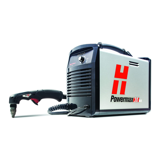
SPECIFICATIONS System description The Powermax30 is a highly portable, 30-amp, hand-held plasma cutting system appropriate for a wide range of applications. The standard Powermax30 includes one complete set of the consumables needed for cutting (retaining cap, swirl ring, nozzle, electrode), a spare electrode, a spare nozzle, an air fitting reducer (1/4 FPT x 1/8 NPT), a consumables holder, an Operator Manual, and a Quick Setup Card. -
Page 51: Power Supply Ratings
Clean, dry, oil-free 99.995 % pure Minimum required gas inlet pressure 3.5 scfm @ 65 psi (99.1 l/min @ 4.5 bar and flow Recommended gas inlet flow 4.0 scfm @ 80 psi (113.3 l/min @ 5.5 bar) and flow powermax30 Operator Manual... -
Page 52: Torch Dimensions
1/4 inch (6 mm) at 30 A (35% duty cycle) Maximum capacity 3/8 inch (10 mm) at 30 A (35% duty cycle) Severance capacity 1/2 inch (12 mm) at 30 A (35% duty cycle) Weight 2.1 lbs (1.0 kg) powermax30 Operator Manual... -
Page 53: Symbols And Markings
) constitutes a manufacturer’s declaration of conformity to applicable European directives and standards. Only those versions of Hypertherm products with a CE mark located on or near the data plate have been tested for compliance with the European Low Voltage Directive and the European EMC Directive. - Page 54 SPECIFICATIONS powermax30 Operator Manual...
-
Page 55: Setup
Section 3 SETUP In this section: Unpack the Powermax30 ..........................3-2 Claims .................................3-2 Contents ..............................3-2 Position the power supply..........................3-3 Voltage configurations ............................3-3 Requirements for grounding..........................3-3 Power cord considerations..........................3-4 Power cord and plugs for CSA power supplies ................3-4 Power cord for CE power supplies ......................3-5 Extension cord recommendations ......................3-6... -
Page 56: Unpack The Powermax30
• Claims for damage during shipment – If your unit was damaged during shipment, you must file a claim with the carrier. Hypertherm will furnish you with a copy of the bill of lading upon request. If you need additional assistance, call the nearest Hypertherm office listed in the front of this manual. -
Page 57: Position The Power Supply
SETUP Position the power supply Locate the Powermax30 power supply near a 120 volt or 230 volt power receptacle. Allow at least 10 inches (0.25 m) of space at the front and back of the power supply for proper ventilation. -
Page 58: Power Cord Considerations
SETUP Power cord considerations Powermax30 power supplies are shipped with CSA and CE power cord configurations. Power cord and plugs for CSA power supplies The power cords on the CSA power supplies are shipped with a 120V/15A (NEMA 5-15P) plug adapter and a 240V/20A (NEMA 6-50P) plug adapter in addition to the twist-lock 240V/20A (NEMA L6-20P) plug wired to the system. -
Page 59: Power Cord For Ce Power Supplies
2. Remove each wire’s insulation in order to make good contact with the plug terminals. 3. Make the connections, reinstall the outer shell and cord grip, and tighten the cord grip’s screws. Screws should be snug, but not overly tight. powermax30 Operator Manual... -
Page 60: Extension Cord Recommendations
25 A Limited arc stretch Powermax30 systems with serial numbers below 30-003132 may shut down and show an error condition (all LEDs flash) when used with a generator that has a higher than normal voltage (greater than 250 VAC). To avoid shutdown, check your generator’s voltage regulator for proper operation. -
Page 61: Gas Supply
SETUP Gas supply The gas supply for the Powermax30 can be shop-compressed or cylinder-compressed. A high- pressure regulator must be used on either type of supply and must be capable of delivering gas to the filter on the power supply at 3.5 scfm @ 65 psi (99.1 l/min @ 4.5... -
Page 62: Additional Gas Filtration
When site conditions introduce moisture, oil or other contaminants into the gas line, use a three- stage coalescing filtration system, such as the Eliminizer filter kit (part number 128647) available from Hypertherm distributors. A three-stage filtering system works as shown below to clean contaminants from the gas supply. -
Page 63: Operation
Power ON the system............................4-4 Hand torch operation ............................4-6 Safety trigger operation ..........................4-6 Hand torch cutting hints..........................4-7 To start a cut from the edge of the workpiece...................4-8 To pierce a workpiece..........................4-9 Cut chart................................4-10 Duty cycle and overheating..........................4-11 Common cutting faults ............................4-11 powermax30 Operator Manual... -
Page 64: Controls And Indicators
OPERATION Controls and indicators The Powermax30 has an ON/OFF rocker switch, an amperage adjustment knob and 4 indicator lights, which are described below. Front Rear Front controls and LEDs Power ON LED (green) Temperature LED (yellow) When illuminated, this LED indicates... -
Page 65: Install The Consumables
With the power switch in the OFF (O) position, verify that the torch consumables are installed as shown. Electrode Swirl ring Nozzle Retaining cap Deflector (optional, only included with the deluxe carrying case). Tighten only by hand. powermax30 Operator Manual... -
Page 66: Attach The Work Clamp
(EMF). Do not attach the work clamp to the portion of the workpiece to be cut away. Work clamp Power ON the system 1. Set the ON/OFF rocker switch to the ON (I) position. powermax30 Operator Manual... - Page 67 2. Adjust the amps knob to the desired cutting current based on the input voltage and circuit size. To operate your Powermax30 system on a 120-volt, 15-amp circuit, do not set the amps higher than 20 (the dark gray part of the dial). See Section 3, Voltage configurations, for more information.
-
Page 68: Hand Torch Operation
• Never point the torch toward yourself or others. Safety trigger operation The Powermax30 is equipped with a safety trigger to prevent accidental firings. When you are ready to cut with the torch, flip the yellow safety trigger forward (toward the torch head) and press the torch trigger as show below. -
Page 69: Hand Torch Cutting Hints
• Pulling the torch along the cut is easier than pushing it. • For straight-line cuts, use a straight edge as a guide. To cut circles, use a template or a radius cutter attachment (a circle cutting guide). powermax30 Operator Manual... -
Page 70: To Start A Cut From The Edge Of The Workpiece
2. Press the torch trigger to start the arc. Pause at the edge until the arc has cut completely through the workpiece. 3. Drag the nozzle lightly across the workpiece to proceed with the cut. powermax30 Operator Manual... -
Page 71: To Pierce A Workpiece
3. Hold the torch in place. When sparks exit from the bottom of the workpiece, the arc has pierced the material. 4. When the pierce is complete, drag the nozzle lightly along the workpiece to proceed with the cut. powermax30 Operator Manual... -
Page 72: Cut Chart
Stainless steel 1397 1/4" Stainless steel 3/8" Stainless steel 18 ga. Aluminum 10135 10 ga. Aluminum 1981 1/4" Aluminum 3/8" Aluminum * To cut material thicker than 1/4 inch (6 mm), start torch at edge of material. powermax30 4-10 Operator Manual... -
Page 73: Duty Cycle And Overheating
• The metal being cut is too thick. • The work clamp is not attached properly to the workpiece. The arc sputters and consumables life is shorter than expected. The cause can be: • Moisture in the gas supply. powermax30 Operator Manual 4-11... - Page 74 OPERATION powermax30 4-12 Operator Manual...
- Page 75 Replace the power cord (CE) ......................5-17 Replace the air filter element.......................5-19 Replacement and accessory parts .......................5-20 Power cords and adapters........................5-20 Accessory parts............................5-20 T30v hand torch assembly ........................5-21 Consumables ............................5-21 Filter regulator............................5-22 Work clamp .............................5-22 Powermax30 labels ..........................5-23 powermax30 Operator Manual...
-
Page 76: Routine Maintenance
Replace any damaged parts. Replace any damaged labels. Inspect the power cord and Inspect the torch lead. plug. Replace if damaged. Replace if damaged. Every 6 months: Clean the inside of the power supply with compressed air or a vacuum. powermax30 Operator Manual... -
Page 77: Inspect The Consumables
If the o-ring is dry, lubricate The surface for damage, it with a thin layer of Torch o-ring wear, or a lack of silicone lubricant. If it is lubrication. cracked or worn, replace it. powermax30 Operator Manual... -
Page 78: Basic Troubleshooting
If you are unable to fix the problem by following this basic troubleshooting guide or if you need further assistance: 1. Call your Hypertherm distributor or authorized Hypertherm repair facility. 2. Call nearest Hypertherm office listed in the front of this manual. Problem Solution The ON/OFF power switch is set to ON •... - Page 79 Contact your distributor or use the information in the front of this book to contact Hypertherm Technical Service. Note: Using a generator with a Powermax30 system that has a serial number below 30-003132 can cause the LEDs to blink if the generator delivers a higher than normal voltage.
- Page 80 The cut quality is poor. • Verify that the torch is being used correctly. See Section 4, Hand torch operation. • Inspect the consumables for wear and replace as necessary. See Inspect the consumables, in this section. powermax30 Operator Manual...
-
Page 81: Repairs
Remove and replace the cover and Nomex® barrier The first step in most maintenance and repair procedures for the Powermax30 is removing the cover and the Nomex barrier. To protect your power supply, it is important to replace both items properly when the maintenance is complete. - Page 82 . Position the handle over the holes in the top of the cover, then use the 2 screws to secure the cover. powermax30 Operator Manual...
-
Page 83: Remove An Endcap
Next to each foot is a raised rib. Front endcap Rear endcap Snap Snap Retaining Retaining screw screw Snap Snap 4. Remove the retaining screw from the bottom of the endcap. powermax30 Operator Manual... - Page 84 8. Repeat steps 5 and 6 on the other corner of the endcap. powermax30 5-10 Operator Manual...
-
Page 85: Disconnect The Torch Lead
3. Compress the hose fitting collar and pull the hose from the fitting to remove the gas hose from the solenoid valve. Front endcap Solenoid valve Hose fitting collar White wire group Red wire group Gas hose powermax30 Operator Manual 5-11... - Page 86 Tip the endcap away from the power supply and press the connector into the slot on the power board. 11. Tighten the torch lead’s strain relief onto the power supply by screwing it into place and reposition the endcap. powermax30 5-12 Operator Manual...
-
Page 87: Replace The Work Lead
(J22) 4. Either remove the front endcap or gently tilt it away from the power supply. From the inside of the endcap, unscrew the nut that secures the strain relief to the endcap. powermax30 Operator Manual 5-13... - Page 88 10. Replace the Nomex barrier and slide the cover back onto the power supply. Position the handle over the holes in the top of the cover, then use the 2 screws to secure the cover. 11. Reconnect the electrical power and the gas supply. powermax30 5-14 Operator Manual...
-
Page 89: Replace The Power Cord (Csa)
Carefully pull the connector for the white wire away from the power switch to disconnect it. You can use needlenose pliers or a straight screwdriver to ease it out, if necessary. 5. Remove the black wire the same way. Single phase Black White wire White Black wire Green powermax30 Operator Manual 5-15... - Page 90 14. Position the wires in the wire chase up the side of the endcap and out of the way of the power board. Once the wires are in place, tighten the strain relief’s retention nut on the outside of the endcap. powermax30 5-16 Operator Manual...
-
Page 91: Replace The Power Cord (Ce)
Carefully pull the connector for the blue wire away from the power switch to disconnect it. You can use needlenose pliers or a straight screwdriver to ease it out, if necessary. Single phase Brown Blue Blue wire Brown wire Green/yellow powermax30 Operator Manual 5-17... - Page 92 12. Press the connector for the brown wire onto the pin on the upper left side of the power switch. 13. Press the connector for the blue wire onto the pin on the upper right side of the power switch. powermax30 5-18 Operator Manual...
-
Page 93: Replace The Air Filter Element
4. Unscrew the nut that holds the air filter in the bracket. Tip the bottom of the air filter away from the power supply. 5. Unscrew the filter bowl from the body and remove it. Bracket Filter bowl Drain hose powermax30 Operator Manual 5-19... -
Page 94: Replacement And Accessory Parts
The following sections list part numbers and quantities needed for common replacement parts for the Powermax30. Power cords and adapters Part number Description Quantity 228142 Kit: Powermax30 CSA power cord and adapters 229135 Powermax30 CSA power cord 229132 Extension power cord subassembly: 120V/15A adapter 229133 Extension power cord subassembly: 240V/20A adapter... -
Page 95: T30V Hand Torch Assembly
Kit: torch lead replacement, 15 ft / 4.5 m * The torch assembly also includes one set of the consumables listed below. Consumables Part number Description Quantity 220478 Electrode 220479 Swirl ring 220483 Retaining Cap 220480 Nozzle 220569 Deflector (optional) powermax30 Operator Manual 5-21... -
Page 96: Filter Regulator
MAINTENANCE AND PARTS Filter regulator Part Item number Description Qty. 011106 Air filter element Work clamp Item Part number Description Qty. 123868 Work cable with clamp, 15 ft / 4.6 m powermax30 5-22 Operator Manual... -
Page 97: Powermax30 Labels
MAINTENANCE AND PARTS Powermax30 labels Part number Description 228097 Kit: Powermax30 labels, CE 228098 Kit: Powermax30 labels, CSA T30v CONSUMABLE PARTS Pièces Consommables T30v 220569* 220483 220480 220479 220478 *Optional Data plate *En option Plaque signalètique PN 110583 Rev. A... - Page 98 MAINTENANCE AND PARTS powermax30 5-24 Operator Manual...
Need help?
Do you have a question about the powermax30 and is the answer not in the manual?
Questions and answers