Sign In
Upload
Manuals
Brands
Hydronix Manuals
Accessories
Hydro-Probe XT
Hydronix Hydro-Probe XT Manuals
Manuals and User Guides for Hydronix Hydro-Probe XT. We have
3
Hydronix Hydro-Probe XT manuals available for free PDF download: User Manual, Configuration And Calibration Manual, Installation Manual
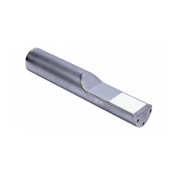
Hydronix Hydro-Probe XT User Manual (67 pages)
Brand:
Hydronix
| Category:
Measuring Instruments
| Size: 1 MB
Table of Contents
Table of Contents
7
Chapter 1 Introduction
11
Figure 1: the Hydro-Probe XT
11
Introduction
12
Measuring Techniques
12
Figure 2: Connecting the Sensor (Overview)
13
Sensor Connection and Configuration
13
Chapter 2 Mechanical Installation
15
General to All Applications
15
Figure 3: Hydro-Probe XT Mounting Angle and Material Flow
15
Figure 4: Fitting a Deflection Plate to Prevent Damage
15
Positioning the Sensor
16
Figure 5: Overhead View of Hydro-Probe XT Mounted in a bin
16
Figure 6: Mounting the Hydro-Probe XT in the Neck of the bin
16
Figure 7: Mounting the Hydro-Probe XT in the bin Wall
17
Figure 8: Mounting the Hydro-Probe XT in Large Bins
17
Figure 9: Mounting the Hydro-Probe XT in a Vibratory Feeder
18
Figure 10: Mounting the Hydro-Probe XT on a Conveyor Belt
19
Figure 11 - Mounting the Hydro-Probe XT in an En-Masse Conveyor
20
Figure 12 - Mounting the Hydro-Probe XT in a Screw Conveyor
21
Installing the Sensor
22
Figure 13: the Standard Mounting Sleeve (Part no 0025)
22
Figure 14: the Extension Mounting Sleeve (Part no 0026)
22
Figure 15: Flanged Mounting Sleeve (Part Number 0024A)
23
Corrosion Protection
24
Figure 16: Hydro-Probe Installed under an Aggregate bin
24
Figure 17: Hydro-Probe Installed in an Extension Mounting Sleeve
25
Figure 18: Hydro-Probe Installed with a Drip Loop
25
Figure 19: Deflector Plate
25
Chapter 3 Electrical Installation and Communication
27
Installation Guidelines
27
Analogue Outputs
27
Figure 20: 0975A Sensor Cable Connections
28
RS485 Multi-Drop Connection
29
Figure 21: RS485 Multi-Drop Connection
29
Figure 22: Correct RS485 Cable Networks
29
Figure 23: Incorrect RS485 Cabling
29
Hydronix Interface Units
30
Digital Input/Output Connection
30
Figure 24: Internal/External Excitation of Digital Input 1 & 2
30
Figure 25: Activation of Digital Output 2
30
Connecting to a PC
31
Figure 26: RS232/485 Converter Connections (0049B)
31
Figure 27: RS232/485 Converter Connections (0049A)
31
Figure 28: RS232/485 Converter Connections (Sensor Interface Module)
32
Figure 29: Ethernet Adapter Connections (EAK01)
33
Figure 30: Ethernet Power Adapter Kit Connections (EPK01)
33
Figure 31: Maximum Number of Sensor Connections Dependent Upon Ambient Temperature
34
Chapter 4 Configuration
35
Configuring the Sensor
35
Analogue Output Setup
35
Figure 32: Guidance for Setting Output Variables
36
Digital Inputs/Output Setup
37
Filtering
38
Alternative Measurement Techniques
39
Figure 33: Relationship of Moisture % to Unscaled Values
40
Chapter 5 Sensor Integration and Calibration
43
Sensor Integration
43
Sensor Calibration
43
Figure 34: Calibrations for Two Different Materials
43
Figure 35: Calibration Inside the Hydro-Probe XT
45
Figure 36: Calibration Inside the Control System
46
Figure 37: Example of Good Material Calibration
49
Figure 38: Examples of Poor Material Calibration Points
50
Chapter 6 Optimising Sensor and Process Performance
51
General to All Applications
51
Routine Maintenance
51
Chapter 7 Sensor Diagnostics
53
Sensor Diagnostics
53
Chapter 8 Technical Specification
59
Technical Specifications
59
Chapter 9 Frequently Asked Questions
61
Appendix A Default Parameters
63
Default Parameters
63
Appendix B Document Cross Reference
65
Document Cross Reference
65
Advertisement
Hydronix Hydro-Probe XT Configuration And Calibration Manual (53 pages)
Moisture Sensor
Brand:
Hydronix
| Category:
Accessories
| Size: 0 MB
Table of Contents
Table of Contents
7
Chapter 1 Introduction
11
Introduction
11
Figure 1: Connecting the Sensor (Overview)
13
Chapter 2 Configuration
15
Configuring the Sensor
15
Analogue Output Setup
15
Figure 2: Guidance for Setting Output Variable
15
Digital Inputs/Output Setup
17
Averaging Parameters
19
Filtering
20
Typical Moisture Trace from a Hydronix Moisture Sensor in Flowing Material
21
Figure 3: Raw and Filter Include Sensor Output
21
Figure 4: Raw Unscaled Moisture Trace in Flowing Material
21
Figure 5: Graph Showing the Filtered Signal
21
Filtering the Signal When Used in a Mixer Application
22
Figure 6: Typical Moisture Curve
22
Figure 7: Graph Showing Raw Signal During MIX Cycle
22
Figure 8: Filtering the RAW Unscaled Signal (1)
23
Figure 9: Filtering the RAW Signal (2)
23
Figure 10: Relationship of Unscaled Values to Moisture
25
Outputting the Sensor Data
26
Figure 11: Data Arrangement in the Sensor
26
Figure 12: None Specified Output Selection
27
Figure 13: Legacy Output Selection
27
Chapter 3 Sensor Integration and Material Calibration
29
Sensor Integration
29
Introduction to Material Calibration
29
Figure 14: Calibrations for 3 Different Materials
29
Figure 15: Typical Calibration Results
30
SSD Coefficient and SSD Moisture Content
31
Storing Calibration Data
31
Figure 16: Calibration Inside the Sensor
31
Calibration Procedure for Flowing Material (Linear)
32
Figure 17 - Calibration Inside the Control System
32
Good/Bad Calibration
34
Figure 18 - Example of Good Material Calibration
34
Quadratic Calibration
35
Figure 19 - Examples of Poor Material Calibration Points
35
Calibrating a Sensor in a Mixer
36
Figure 20: Example of a Good Quadratic Calibration
36
Figure 21: Example of a Bad Quadratic Calibration
36
Brix Calibration
38
Figure 22: Example of a Good Brix Calibration
39
Figure 23: Example of a Bad Brix Calibration
39
Chapter 4 Best Practices
41
General to All Applications
41
Chapter 5 Sensor Diagnostics
43
Sensor Diagnostics
43
Chapter 6 Frequently Asked Questions
49
Appendix A Document Cross Reference
51
Document Cross Reference
51
Hydronix Hydro-Probe XT Installation Manual (27 pages)
Brand:
Hydronix
| Category:
Measuring Instruments
| Size: 0 MB
Table of Contents
Table of Contents
7
Chapter 1 Hydro-Probe Installation
11
Figure 1: the Hydro-Probe Sensor
11
General to All Applications
12
Figure 2: Hydro-Probe Mounting Angle and Material Flow
12
Figure 3: Fitting a Deflection Plate to Prevent Damage
12
Positioning the Sensor
13
Figure 4: Overhead View of Hydro-Probe Mounted in a bin
13
Figure 5: Mounting the Hydro-Probe in the Neck of the bin
13
Figure 6: Mounting the Hydro-Probe in the bin Wall
14
Figure 7: Mounting the Hydro-Probe in Large Bins
14
Figure 8: Vibratory Feed Mounting
15
Figure 9: Mounting the Hydro-Probe on a Conveyor Belt
15
Figure 10: Hydro-Probe Angled at 45° to Reduce Build-Up
16
Figure 11: Mounting the Hydro-Probe in an En-Masse Conveyor
16
Figure 12: Mounting the Hydro-Probe in a Screw Conveyor
17
Figure 13: Hydro-Probe in Ducting
17
Installing the Sensor
18
Figure 14: the Standard Mounting Sleeve (Part no 0025)
18
Figure 15: the Extension Mounting Sleeve (Part no 0026)
18
Figure 16: Flanged Mounting Sleeve (Part Number 0024A)
19
Chapter 2 Corrosion Protection
21
Corrosion Protection
21
Figure 17: Hydro-Probe Installed under an Aggregate bin
21
Figure 18: Hydro-Probe Installed in an Extension Mounting Sleeve
21
Figure 19: Hydro-Probe Installed with a Drip Loop
22
Figure 20: Hydro-Probe Protection Cover
22
Chapter 3 Technical Specification
23
Technical Specification
23
Appendix A Document Cross Reference
25
Document Cross Reference
25
Advertisement
Advertisement
Related Products
Hydronix Hydro-Probe SE
Hydronix Hydro-Probe
Hydronix Hydro-Probe Orbiter
Hydronix Hydro-Mix HT
Hydronix Hydro-Mix
Hydronix Hydro-Control VI
Hydronix Hydro-View
Hydronix Hydro-Hub
Hydronix Hydro-MIX XT Skid
Hydronix HD0333
Hydronix Categories
Accessories
Measuring Instruments
Adapter
Control Unit
Touchscreen
More Hydronix Manuals
Login
Sign In
OR
Sign in with Facebook
Sign in with Google
Upload manual
Upload from disk
Upload from URL