Sign In
Upload
Manuals
Brands
HP Manuals
Measuring Instruments
16501A LOGIC
HP 16501A LOGIC Manuals
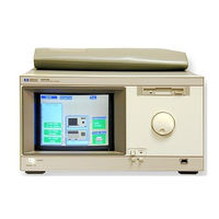
Manuals and User Guides for HP 16501A LOGIC. We have
4
HP 16501A LOGIC manuals available for free PDF download: Programmer's Manual, Service Manual, User Manual, Setting Up
HP 16501A LOGIC Programmer's Manual (252 pages)
Logic Analysis System
Brand:
HP
| Category:
Measuring Instruments
| Size: 2.35 MB
Table of Contents
5
Table of Contents
15
1 Introduction to Programming
16
Introduction
17
Talking to the Logic Analysis System
18
Talking to Individual System Modules
18
Initialization
20
Instruction Syntax
20
Output Command
21
Device Address
21
Instructions
22
Instruction Terminator
23
Header Types
24
Duplicate Keywords
25
Query Usage
26
Program Header Options
27
Parameter Data Types
29
Selecting Multiple Subsystems
30
Receiving Information From the Logic Analysis System
31
Response Header Options
32
Response Data Formats
33
String Variables
34
Numeric Base
34
Numeric Variables
35
Definite-Length Block Response Data
36
Multiple Queries
37
System Status
39
2 Programming Over HP-IB
41
Interface Capabilities
41
Command and Data Concepts
41
Talk/Listen Addressing
42
HP-IB Bus Addressing
43
Local, Remote, and Local Lockout
44
Bus Commands
45
3 Programming Over RS-232-C
47
Interface Operation
47
RS-232-C Cables
48
Minimum Three-Wire Interface with Software Protocol
49
Extended Interface with Hardware Handshake
50
Cable Examples
51
Configuring the Logic Analysis System Interface
52
Interface Capabilities
53
RS-232-C Bus Addressing
54
Lockout Command
55
4 Programming Over LAN
57
Communicating with the HP 16500C
57
LAN Addressing
58
Password Protection and File Protection
58
Permission Levels: Control and Data
59
Controlling the HP 16500C
60
Echoing Commands
61
Copying Command Files
62
Writing to \System\Program From a Program
65
Sending Commands to the HP 16500C Socket
67
Lockout Command
69
5 Programming and Documentation Conventions
71
Truncation Rule
72
Infinity Representation
72
Sequential and Overlapped Commands
72
Response Generation
72
Syntax Diagrams
73
Notation Conventions and Definitions
74
The Command Tree
76
Tree Traversal Rules
78
Command Set Organization
78
Subsystems
80
Program Examples
81
Message Communication and System Functions
84
6 Message Communication and System Functions Protocols
85
Syntax Diagrams
87
Syntax Overview
91
Status Reporting
94
7 Status Reporting Event Status Register
94
Service Request Enable Register
94
Bit Definitions
96
Key Features
98
Serial Poll
99
Parallel Poll
101
Polling HP-IB Devices
101
Configuring Parallel Poll Responses
102
Conducting a Parallel Poll
103
Disabling Parallel Poll Responses
103
HP-IB Commands
105
8 Error Messages
107
Device Dependent Errors
107
Command Errors
108
Execution Errors
108
Internal Errors
109
Query Errors
113
9 Common Commands
117
CLS (Clear Status)
118
ESE (Event Status Enable)
119
ESR (Event Status Register)
121
IDN (Identification Number)
121
IST (Individual Status)
123
OPC (Operation Complete)
124
OPT (Option Identification)
125
PRE (Parallel Poll Enable Register Enable)
126
RST (Reset)
127
SRE (Service Request Enable)
128
STB (Status Byte)
129
TRG (Trigger)
130
TST (Test)
131
WAI (Wait)
138
10 Mainframe Commands Beeper
139
Capability
140
Cardcage
142
CESE (Combined Event Status Enable)
143
CESR (Combined Event Status Register)
145
EOI (End or Identify)
145
LER (LCL Event Register)
146
Lockout
147
Menu
148
MESE<N> (Module Event Status Enable)
150
MESR<N> (Module Event Status Register)
151
Rmode
152
RTC (Real-Time Clock)
153
Select
155
Setcolor
156
Start
157
Stop
158
Xwindow
159
11 System Subsystem
163
Data
164
DSP (Display)
165
Error
166
Header
167
Longform
168
Print
170
Setup
173
12 Mmemory Subsystem
179
Autoload
180
Catalog
181
CD (Change Directory)
182
Copy
183
Download
185
Identify
186
Initialize
187
Load[:Config]
188
LOAD :Iassembler
189
Mkdir (Make Directory)
190
MSI (Mass Storage Is)
191
Pack
192
Purge
193
PWD (Present Working Directory)
194
Rename
195
Store [:Config]
196
Upload
197
Volume
199
13 Intermodule Subsystem
203
Intermodule
204
Delete
205
Htime
206
Inport
207
Insert
208
Outdrive
208
Outpolar
209
Outtype
210
Portedge
211
Portlev
212
Skew<N
213
Tree
215
Ttime
217
14 Tgtctrl Subsystem
221
Tgtctrl
222
All
223
Available
224
Bits
225
Curstate
225
Drive
226
Laststate
227
Name
228
Pulse
228
Signal
229
Sigstatus
230
States
231
Step
231
Toggle
232
Type
233
Part 3 Programming Examples
233
15 Programming Examples
237
Transferring the Mainframe Configuration
240
Checking for Intermodule Measurement Completion
241
Sending Queries to the Logic Analysis System
243
Getting ASCII Data with Print? ALL Query
244
Reading the Disk with the Catalog? ALL Query
245
Reading the Disk with the Catalog? Query
246
Printing to the Disk
247
Index
Advertisement
HP 16501A LOGIC Service Manual (144 pages)
Logic Analysis System
Brand:
HP
| Category:
Measuring Instruments
| Size: 14.41 MB
Table of Contents
2
Service Manual
3
Table of Contents
8
General Information Page
9
Introduction
9
Instruments Covered By This Manual
10
Safety Considerations
10
Product Description
10
Accessories Supplied
11
Accessories Available
11
Operating Characteristics
11
Recommended Test Equipment
12
Operating Characteristics
14
Dimensional Detail
15
Recommended Test Equipment
16
Installation Page
17
Introduction
17
Safety Considerations
17
Initial Inspection
17
Operating Disk Installation
17
Power Requirements
17
Line Voltage Selection
18
Power Cable
18
Line Voltage Selection
19
Power Cord Configurations
20
User Interface
21
HP-IB Interfacing
21
HP-IB Address Selection
21
HP-IB Interface Connector
22
System Configuration Menu
22
HP-IB Configuration Menu
23
HP-IB Configuration with Keypad
24
HP-IB Interface Functions
24
RS-232C Interface
24
HP 16500A HP-IB Functions
25
RS-232C Signal Definitions
26
Baud Rate Selection
26
System Configuration Menu
26
RS-232C Configuration Menu
27
Baud Rate Pop-Up Menu
27
Configuration
28
Degaussing the Display
28
Operating Environment
28
Storage and Shipment
28
Packaging
28
Tagging for Service
28
Cleaning Requirements
29
HP 16501A Expansion Frame Installation
30
Endplate Overlap
32
System Configuration Menu
33
Performance Tests Page
34
Introduction
35
Adjustments Page
36
Introduction
36
Degaussing the Display
36
Safety Considerations
37
Adjustment Test Patterns
37
System Configuration Menu
37
Accessing the Test System
38
Loading the Test System
38
Test System Configuration
39
Selecting Mainframe Test Menu
40
Selecting the Test Patterns
40
Exiting Mainframe Test System
41
Exiting Test System Configuration
42
Color Display Module Adjustments
43
CRT Module Adjustment Flow Diagram
44
PIN AMP Adjustment
45
Bottom Rail Removal
46
PIN PHASE Adjustment
48
Purity Magnet Centering
49
Purity Magnet Adjustment Raster
50
Landing and Purity Adjustment Guide
51
Static Convergence
52
Y BOW Adjustment
52
Y BOW CROSS Adjustment
53
V.STAT TOP Adjustment
53
V.STAT BOTTOM Adjustment
54
H.AMP Adjustment
54
H.TILT Adjustment
56
Replaceable Parts Page
56
Introduction
57
Abbreviations
57
Exchange Assemblies
57
Introduction
57
Ordering Information
57
Replaceable Parts List
58
Direct Mail Order System
59
Reference Designator and Abbreviations
61
HP 16500A Replaceable Parts
65
HP 16501A Assembly Parts
66
HP 16501A Replaceable Parts
67
HP 16501A Chassis Parts
69
Service Page
70
Introduction
70
Safety Considerations
70
Service Test Equipment Required
70
Theory of Operation
71
HP 16500A/16501A System Overview
73
Microprocessor Block Diagram
75
Power-Up Tests
77
Mainframe Tests
77
System Configuration
78
Accessing the Test System
78
Loading the Test System Software
79
Test System Configuration
79
Mainframe Test Menu
80
All System Test
81
Selecting the Color Display Patterns
82
Mainframe Test Menu
82
ROM Test Screen
83
Choosing the Single or Repetitive Mode
83
ROM Test with Test Results
84
Exiting the Mainframe Test System
84
Exiting Test Configuration
85
Reloading the Mainframe System
88
Troubleshooting
89
Troubleshooting Flowchart 1
90
Troubleshooting Flowchart 2
91
Troubleshooting Flowchart 3
92
Troubleshooting Flowchart 3 (Continued)
93
Troubleshooting Flowchart 4
94
Troubleshooting Flowchart 5
95
Troubleshooting Flowchart 6
96
Troubleshooting Flowchart 7
97
Troubleshooting Flowchart 8
98
Troubleshooting Flowchart 9
99
Troubleshooting Flowchart 10
100
Troubleshooting Flowchart 11
101
Troubleshooting Flowchart 12
103
Cable Pin Numbers
104
Color Module to Microprocessor Cable
104
Horizontal and Vertical Sync Signals
106
Power Supply Check
107
Power Supply Voltages
108
Power Supply Pins
110
HP 1651B Format Menu
110
Probe Tip Connections
111
Expander Test Screen
112
HP 1651B Test Screen
113
Probe Tip Connections
115
Repair
115
Replaceable Assemblies
116
Tools Required
116
Cover Removal
117
Power Supply Replacement
118
Power Supply Replacement
119
Mother Board Replacement
120
Mother Board Replacement
121
Rear Fan Replacement
122
Rear Fan Replacement
123
Side Fan Replacement
124
Side Fan Replacement
125
Rear Disk Drive Replacement
126
Rear Disk Drive Replacement
127
Front Disk Drive Replacement
128
Front Disk Drive Replacement
129
Microprocessor Board Replacement
130
Microprocessor Board Replacement
131
Front-Panel Board Replacement
132
Front-Panel Board Replacement
133
Color Display Module Replacement
134
Color Display Module Removal
135
Transferring Parts
138
Color Display Module Installation
139
Expansion Interface Board Replacement
140
Expansion Interface Board Replacement
141
Mainframe Interface Board Replacement
141
Endplate Overlap
142
Mainframe Interface Board Replacement
HP 16501A LOGIC User Manual (141 pages)
Logic Analysis System
Brand:
HP
| Category:
Analytical Instruments
| Size: 1.78 MB
Table of Contents
5
Chapter 1, "Triggering," Shows You How to Set Up the Analyzer to Trigger On the
7
Table of Contents
11
1 Triggering
13
To Store and Time the Execution of a Subroutine
15
To Trigger On the Nth Iteration of a Loop
17
To Trigger On the Nth Recursive Call of a Recursive Function
19
To Trigger On Entry to a Function
21
To Capture a Trace of Activity Associated with a Write of Known Bad Data to a Particular Variable
22
To Trigger On a Loop That Occasionally Runs Too Long
23
To Verify That All Stacks and Registers Are Restored Correctly before Exiting a Subroutine
25
To Trigger After All Status Bus Lines Finish Transitioning
26
To Find the Nth Occurrence of Asserting a Chip Select Line
27
To Verify That the Chip Select Line of a Memory Chip Is Strobed After the Address On the Address Bus Is Stable
28
To Trigger When Expected Data Does Not Appear On the Data Bus From a Remote Device When Requested
30
To Test Minimum and Maximum Pulse Limits
32
To Detect a Handshake Violation
33
To Detect Bus Contention
34
Cross-Arming Trigger Examples
35
To Examine Software Execution When a Timing Violation Occurs
36
To Look at Control and Status Signals During Execution of a Routine
37
2 Intermodule Measurements
40
Intermodule Measurement Examples
41
To Set Up a Group Run of Modules Within the HP 16500B
43
To Start a Group Run of Modules From an External Trigger Source
45
To Start an External Instrument On Command From a Module Within the HP 16500 and 16501 Mainframe
47
To See the Status of a Module Within an Intermodule Measurement
48
O See Time Cor Re La Tion of Each Mod Ule Within an in Ter Mod Ule Meas Ure Ment
49
To Use a Timing Analyzer to Detect a Glitch
50
To Capture the Waveform of a Glitch
51
O Cap Ture State Flow Show Ing How Your Tar Get Sys Tem Pro Cesses an in Ter Rupt
53
Using Stimulus-Response to Test a Circuit
55
To Use a State Analyzer to Trigger Timing Analysis of a Count-Down On a Set of Data Lines
56
To Use Two State Analyzers to Monitor the Activity of Coprocessors in a Target System
57
Special Displays
58
To Interleave Trace Lists
60
To View Trace Lists and Waveforms Together On the Same Display
62
Skew Adjustment
63
To Adjust for Minimum Skew Between Two Modules Involved in an Intermodule Measurement
65
3 File Management
67
Transferring Files Using the Flexible Disk Drive
68
To Save a Measurement Configuration
70
To Load a Measurement Configuration
72
To Save a Trace List in ASCII Format
74
To Save a Menu or Measurement As a Graphic Image
76
To Load System Software
77
Using the HP 16500L LAN Interface
78
To Set Up the HP 16500B
80
To Transfer Data Files From the HP 16500B System to Your Computer
82
To Transfer Graphics Files From the HP 16500B System to Your Computer
83
4 Concepts
85
The Trigger Sequencer
92
The Inverse Assembler
95
Configuration Translation for Analyzer Modules
99
5 If You Have a Problem
101
Analyzer Problems
101
Intermittent Data Errors
101
Unwanted Triggers
102
No Setup/Hold Field On Format Screen
102
No Activity On Activity Indicators
102
Capacitive Loading
102
No Trace List Display
104
Preprocessor Problems
104
Target System Will Not Boot Up
105
Slow Clock
105
Erratic Trace Measurements
107
Inverse Assembler Problems
107
No Inverse Assembly or Incorrect Inverse Assembly
108
Inverse Assembler Will Not Load or Run
109
Intermodule Measurement Problems
109
An Event Wasn't Captured By One of the Modules
110
Messages
110
Default Calibration Factors Loaded" (HP 16540, 16541, and 16542)
110
Inverse Assembler Not Found
111
"Measurement Initialization Error
112
"No Configuration File Loaded
112
"Selected File Is Incompatible
112
"Slow or Missing Clock
113
"State Clock Violates Overdrive Specification
113
Time From Arm Greater Than 41.93 Ms
Advertisement
HP 16501A LOGIC Setting Up (32 pages)
Logic Analysis System
Brand:
HP
| Category:
Analytical Instruments
| Size: 2.39 MB
Table of Contents
4
Table of Contents
6
Chapter 1
6
Getting Ready to Operate
6
Initial Inspection
6
Manuals and Disks
7
Standard Accessories
8
Operating Environment
8
Ventilation Requirements
8
Power Requirements
9
The Yellow Shipping Disks
10
Selecting the Proper Line Voltage
11
Checking for the Correct Fuse
12
Getting Power to the Instrument
14
Chapter 2
14
Turning On the HP 16500A/16501A
14
Installing the Operating System Disk
16
Connecting the Optional Mouse
19
Connecting the Optional Keyboard
24
The Line Switch and Power Standby Switch
25
Loading the Operating System
26
The System Configuration Menu
27
Brightness and Background Controls
27
The Tilt Stand
28
User Interfaces
30
Chapter 3
30
Additional Information
30
Cleaning Requirements
30
The Storage and Shipment Environment
31
Tagging the Instrument for Service
31
Repacking the Instrument
32
What's Next
Share and save
Advertisement
Related Products
HP 16500A
HP 1650B
HP HP 1650A
HP 1653B
HP 16550A
HP 1651B
HP 16554A
HP 16555A
HP 16555D
HP HP 1651A
HP Categories
Desktop
Laptop
Server
Monitor
Switch
More HP Manuals
Login
Sign In
OR
Sign in with Facebook
Sign in with Google
Upload manual
Upload from disk
Upload from URL