Table of Contents
Advertisement
Quick Links
Advertisement
Table of Contents

Related Manuals for HP 16500C


Summary of Contents for HP 16500C
- Page 1 Service Guide Publication number 16500-97019 First edition, November 1996 For Safety information, Warranties, and Regulatory information, see the pages at the end of the book. © Copyright Hewlett-Packard Company 1987 – 1996 All Rights Reserved. HP 16500C/16501A Logic Analysis System...
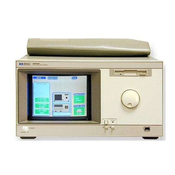
- Page 2 HP 16500C/16501A Logic Analysis System The HP 16500C is the mainframe of the Logic Analysis System, and the HP 16501A is the expansion frame. The HP 16500C/16501A is of a modular structure using plug-in cards with a wide range of data acquisition and stimulus capabilities.
- Page 3 The HP 16500C Logic Analysis System...
- Page 4 In This Book This book is the service guide for the HP 16500C/16501A Logic Analysis System and is divided into eight chapters. Chapter 1 contains information about the instrument and includes accessories for the instrument, specifications and characteristics of the instrument, and a list of the equipment required for servicing the instrument.
-
Page 5: Table Of Contents
To clean the logic analysis system 2-5 To test the logic analysis system 2-5 To install modules 2-6 To connect the HP 16501A Expansion Frame 2-7 3 Testing Performance To perform the power-up tests 3-3 To perform the self-tests 3-4... - Page 6 To return assemblies 6-21 7 Replaceable Parts Replaceable Parts Ordering 7-2 Replaceable Parts List Description 7-3 HP 16500C Exploded View and Replaceable Parts 7-4 HP 16501A Exploded View and Replaceable Parts 7-9 8 Theory of Operation Block-Level Theory 8-3 The HP 16500C Logic Analysis System 8-3...
-
Page 7: General Information
Accessories 1–2 Specifications 1–3 Characteristics 1–3 Recommended Test Equipment 1–6 General Information... -
Page 8: Accessories
Symbol Utility Software Filler Panels Quantity depends on how many modules are ordered with the HP 16500C/16501A Accessories Available Other accessories available for the HP 16500C/16501A Logic Analysis System are listed in the Accessories for HP Logic Analyzers brochure. 1–2... -
Page 9: Specifications
RS-232-C Configurations Protocols: XON/XOFF, Hardware; Data bits: 8; Stop bits: 1, 1 1/2, 2; Parity: none, odd, or even; Baud rates: 110, 300, 600, 1200, 2400, 4800, 9600, 19200. HP-IB Interface Functions SH1, AH1, T5, TE0, L3, LE0, SR1, RL1, PP1, DC1, DT1, C0 and E2. - Page 10 Shipping 19.9 kg (44 lbs) + [3.6 kg (8 lbs) x number of optional cards installed]. Power Requirements HP 16500C 115 V/230 V, -22% to +10%, 48 to 66 Hz, 475 W max. HP 16501A 115 V/230 V, -22% to +10%, 48 to 66 Hz, 420 W max.
- Page 11 General Information Characteristics Dimensions Refer to the following figure for dimensional detail. Dimensional Detail 1–5...
-
Page 12: Recommended Test Equipment
General Information Recommended Test Equipment Recommended Test Equipment Equipment Required Equipment Critical Specifications Recommended Model/Part Oscilloscope 100 MHz Bandwidth HP 54600B Voltmeter HP E2373A *A = Adjustment P = Performance Tests T = Troubleshooting 1–6... -
Page 13: Preparing For Use
To set the line voltage 2–4 To degauss the display 2–5 To clean the logic analysis system 2–5 To test the logic analysis system 2–5 To install modules 2–6 To connect the HP 16501A Expansion Frame 2–7 Preparing for Use... -
Page 14: To Inspect The Logic Analysis System
Preparing For Use This chapter gives you instructions for preparing the logic analysis system for use. Power Requirements The logic analysis system mainframe requires a power source of either 115 Vac or 230 Vac, –22 % to +10 %, single phase, 48 to 66 Hz, 475 W maximum power. The logic analysis system expansion frame requires a power source of either 115 Vac or 230 Vac, –22 % to +10 %, single phase, 48 to 66 Hz, 420 W maximum power. -
Page 15: To Apply Power
To select a field on the mainframe screen, use the touchscreen. For more information about the logic analysis system interface, refer to the HP 16500C/16501A Logic Analysis System User’s Reference. • To set up for a network or for use with other equipment, refer to the HP 16500C/16501A Logic Analysis System User’s Reference. -
Page 16: To Set The Line Voltage
To set the line voltage To set the line voltage When shipped from HP, the line voltage selector is set and an appropriate fuse is installed for operating the instrument in the country of destination. To operate the instrument from a power source other than the one set, perform the following steps. -
Page 17: To Degauss The Display
Preparing for Use To degauss the display To degauss the display • If the mainframe has been subjected to strong magnetic fields, the CRT might become magnetized and display data might become distorted. To correct this condition, degauss the CRT with a conventional, external-television-type degaussing coil. -
Page 18: To Install Modules
Preparing for Use To install modules To install modules The following steps give general instructions for installing modules into the mainframe or the expansion frame of the system. Electrostatic discharge can damage electronic components. Use grounded wriststraps and C A U T I O N mats when performing any service to modules. -
Page 19: To Connect The Hp 16501A Expansion Frame
To connect the HP 16501A Expansion Frame To connect the HP 16501A Expansion Frame The HP 16501A Expansion Frame includes an interface cable to connect to the HP 16500C mainframe. To install the expansion frame, you need to connect the cable from the mainframe to the expansion frame. - Page 20 2–8...
-
Page 21: Testing Performance
To perform the power-up tests 3–3 To perform the self-tests 3–4 Testing Performance... - Page 22 Refer to the Service Guides of the individual modules for more information. The Logic Analysis System Interface To select a field on the HP 16500C screen, use the touchscreen. For more information about the logic analysis system interface, refer to the HP 16500C/16501A Logic Analysis System User’s Reference.
-
Page 23: To Perform The Power-Up Tests
Testing Performance To perform the power-up tests To perform the power-up tests The logic analysis system automatically performs power-up tests when you apply power to the instrument. The revision number of the boot ROM shows in the upper-right corner of the screen during these power-up tests. -
Page 24: To Perform The Self-Tests
Testing Performance To perform the self-tests To perform the self-tests The self-tests verify the correct operation of the logic analysis system. Self-tests can be performed all at once or one at a time. While testing the performance of the logic analysis system, run the self-tests all at once. - Page 25 Testing Performance To perform the self-tests Install a formatted disk that is not write protected into the flexible disk drive. Select All System Tests. You can run all tests at one time by running All System Tests. To see more details about each test, you can run each test individually.
- Page 26 3–6...
-
Page 27: Calibrating And Adjusting
To prepare the instrument 4–3 To access the test patterns 4–4 To adjust geometry 4–5 To adjust focus, landing, and convergence 4–6 To adjust white balance 4–13 Calibrating and Adjusting... - Page 28 Calibrating and Adjusting This chapter normally gives you instructions for calibrating and adjusting the logic analysis system. Because the HP 16500C/16501A requires no calibration, only adjustment instructions are included. Adjustments The only adjustments to the logic analysis system are adjustments to the color CRT monitor assembly.
-
Page 29: To Prepare The Instrument
Calibrating and Adjusting To prepare the instrument To prepare the instrument Turn power off and remove the power cord. Remove the rear feet and the covers from the mainframe (refer to chapter 6). Before starting the adjustments, mark the position where the potentiometers are set. This helps in returning the adjustments to their original positions if it becomes necessary to restart the procedure. -
Page 30: To Access The Test Patterns
Calibrating and Adjusting To access the test patterns To access the test patterns Some procedures on the following pages ask you to access test patterns. This procedure tells you how to access them and how to exit the test. In the System Configuration menu, touch Configuration, then select Test in the pop-up menu. -
Page 31: To Adjust Geometry
Calibrating and Adjusting To adjust geometry To adjust geometry Display the white cross-hatch test pattern on the CRT. From the Color Display Test menu, select the white, cross-hatch pattern. Preset the front panel brightness control, the leftmost of the two controls beside the display, maximum clockwise. -
Page 32: To Adjust Focus, Landing, And Convergence
Calibrating and Adjusting To adjust focus, landing, and convergence To adjust focus, landing, and convergence Once you have started, you will have to do all four of the procedures in this group: the focus, the landing, and both of the convergence adjustments. Initial Preparation Loosen the deflection yoke clamp screw. - Page 33 Calibrating and Adjusting To adjust focus, landing, and convergence Landing Adjustment Turn the front panel Brightness control fully clockwise. Degauss the CRT by momentarily pressing the Degauss switch located on the instrument rear panel. In some cases, the user’s environment or shipping environment may have caused high levels of magnetization in the CRT.
- Page 34 Calibrating and Adjusting To adjust focus, landing, and convergence Move the deflection yoke forward until the entire raster is green. Landing adjustment is easier if the yoke is moved all the way forward and then moved back until the raster is completely green. Using the Color Purity key, replace the green raster with red and then blue raster, each time checking for proper landing adjustment (color purity of each).
- Page 35 Calibrating and Adjusting To adjust focus, landing, and convergence Static Convergence Disconnect the power from the instrument. Remove the PC board shield cover from the rear of the Color CRT Module by prying evenly on all four sides. Reapply power. Display the white, cross-hatch test pattern on the CRT.
- Page 36 Calibrating and Adjusting To adjust focus, landing, and convergence Dynamic Convergence Display the white, cross-hatch test pattern on the CRT. From the Color Display Test menu, select the white, cross-hatch test pattern. Adjust Y BOW (RV805) located on the bottom PC board to eliminate red, green, and blue bowing at the top and bottom of the center vertical line.
- Page 37 Calibrating and Adjusting To adjust focus, landing, and convergence Adjust V TOP (RV801) and V BOTTOM (RV802) to obtain coincidence of the red, blue, and green at the intersection of the top and bottom horizontal lines with the center vertical line. The VTOP and VBOTTOM adjustments are located on the bottom PC board.
- Page 38 Calibrating and Adjusting To adjust focus, landing, and convergence Adjust H.AMP (RV807) located on the bottom PC board for equal amounts of misconvergence at the right and left sides of the screen. Adjust H.TILT (RV806) located on the bottom PC board for coincidence of red, green, and blue at the right and left sides of the screen.
-
Page 39: To Adjust White Balance
Calibrating and Adjusting To adjust white balance To adjust white balance Provide a blank display on the CRT. From the Color Display Test menu, select a blank (colorless) raster. Preset the front panel brightness and contrast controls to their mechanical centers. On the bottom PC board, set the following adjustments to their mechanical centers. - Page 40 4–14...
-
Page 41: Troubleshooting
To use the flowcharts 5-2 To check the power-up self-tests 5-17 To run the self-tests 5-18 To check the video signals 5-21 To check the power supply LEDs 5-22 To check the power supply voltages 5-23 To test the flexible disk drive voltages 5-24 To test the hard disk drive voltages 5-26 Troubleshooting... -
Page 42: To Use The Flowcharts
Troubleshooting This chapter helps you troubleshoot the logic analysis system to find defective assemblies. The troubleshooting consists of flowcharts, self-test instructions, and tests. This information is not intended for component-level repair. If you suspect a problem, start at the top of the first flowchart. During the troubleshooting instructions, the flowcharts will direct you to perform other tests. - Page 43 Troubleshooting To use the flowcharts Main Troubleshooting Flowchart 1 5–3...
- Page 44 Troubleshooting To use the flowcharts Main Troubleshooting Flowchart 2 5–4...
- Page 45 Troubleshooting To use the flowcharts Color Module Troubleshooting Flowchart 3 5–5...
- Page 46 Troubleshooting To use the flowcharts Color Module Troubleshooting Flowchart 3A (continued) 5–6...
- Page 47 Troubleshooting To use the flowcharts Power-Up Troubleshooting Flowchart 4 5–7...
- Page 48 Troubleshooting To use the flowcharts System Start Troubleshooting Flowchart 5 5–8...
- Page 49 Troubleshooting To use the flowcharts Mainframe Tests Troubleshooting Flowchart 6 5–9...
- Page 50 Troubleshooting To use the flowcharts Power Supply Troubleshooting Flowchart 7 5–10...
- Page 51 Troubleshooting To use the flowcharts HIL Troubleshooting Flowchart 8 5–11...
- Page 52 Troubleshooting To use the flowcharts Flexible Disk Drive Troubleshooting Flowchart 9 5–12...
- Page 53 Troubleshooting To use the flowcharts Hard Disk Drive Troubleshooting Flowchart 10 5–13...
- Page 54 Troubleshooting To use the flowcharts TCP, LAN, 16505A Troubleshooting Flowchart 11 5–14...
- Page 55 Troubleshooting To use the flowcharts Intermodule Troubleshooting Flowchart 12 5–15...
- Page 56 Troubleshooting To use the flowcharts Expansion Frame Troubleshooting Flowchart 13 5–16...
-
Page 57: To Check The Power-Up Self-Tests
Troubleshooting To check the power-up self-tests To check the power-up self-tests The logic analysis system automatically performs power-up self-tests when you apply power to the instrument. The revision number of the operating system shows in the upper-right corner of the screen during these power-up tests. As each test completes, either "passed" or "failed"... -
Page 58: To Run The Self-Tests
Troubleshooting To run the self-tests To run the self-tests Self-tests identify the correct operation of major, functional subsystems of the instrument. You can run all self-tests without accessing the interior of the instrument. If a self-test fails, the troubleshooting flowcharts instruct you to change a part of the instrument. If you just did the power-up self-tests, go to step 2. - Page 59 Troubleshooting To run the self-tests Select ROM Test. The ROM Test screen is displayed. You can run all tests at one time by running All System Tests. To see more details about each test, you can run each test individually. This example shows how to run an individual test. Select Run, then select Single.
- Page 60 Troubleshooting To run the self-tests To exit the ROM Test, select Done. Note that the status changes to Passed or Failed. Install a formatted disk that is not write-protected into the flexible disk drive. Run the remaining All System Tests in the same manner. The Color Display Test is not part of this troubleshooting.
-
Page 61: To Check The Video Signals
Troubleshooting To check the video signals To check the video signals Refer to chapter 6, "Replacing Assemblies," for instructions on how to remove or replace covers and assemblies. Hazardous voltages exist on the power supply, the CRT, and the CRT driver board. This W A R N I N G procedure is to be performed by service-trained personnel aware of the hazards involved, such as fire and electrical shock. -
Page 62: To Check The Power Supply Leds
Troubleshooting To check the power supply LEDs To check the power supply LEDs Refer to chapter 6, "Replacing Assemblies," for instructions to remove or replace covers and assemblies. Hazardous voltages exist on the power supply, the CRT, and the CRT driver board. This W A R N I N G procedure is to be performed by service-trained personnel aware of the hazards involved, such as fire and electrical shock. -
Page 63: To Check The Power Supply Voltages
Troubleshooting To check the power supply voltages To check the power supply voltages Refer to chapter 6, "Replacing Assemblies," for instructions to remove or replace covers and assemblies. Hazardous voltages exist on the power supply, the CRT, and the CRT driver board. This W A R N I N G procedure is to be performed by service-trained personnel aware of the hazards involved, such as fire and electrical shock. -
Page 64: To Test The Flexible Disk Drive Voltages
Model/Part Digitizing Oscilloscope > 100 MHz Bandwidth HP 54600B Turn off the instrument, then disconnect the power cable. Remove the instrument cover and the flexible disk drive. Reconnect the disk drive data cable and disk drive power cable to the rear of the disk drive. - Page 65 Troubleshooting To test the flexible disk drive voltages Check for the following voltages and signals using an oscilloscope. Disk Drive Voltages Signal Signal Signal Description Description Description Ground Write Gate Ground Ground Track 00 Motor On Ground Ground Write Protect Direction Ground Ground...
-
Page 66: To Test The Hard Disk Drive Voltages
Model/Part Digitizing Oscilloscope > 100 MHz Bandwidth HP 54600B Turn off the instrument, then remove the power cable. Remove both the top and bottom covers of the mainframe and set the mainframe on its side with the strap handle facing up. - Page 67 Troubleshooting To test the hard disk drive voltages Disk Drive Voltages Signal Description Signal Description Signal Description Reset Data +5 V Ground Data Ground Data Data Interrupt Request Data Data Data Ground Address Data (connector key pin) Data Address Data Ground Address Data...
- Page 68 5–28...
-
Page 69: Replacing Assemblies
To remove and replace the Optional modules or filler panels 6-3 Covers 6-4 Flexible disk drive 6-5 Power supply 6-6 Rear fan 6-8 Side fan 6-9 Hard disk drive 6-10 Microprocessor board (CPU) 6-11 SIMM memory 6-12 I/O board assembly 6-13 Expansion interface board 6-14 Mother board 6-15 Front-panel board 6-17... - Page 70 Replacing Assemblies This chapter contains the instructions for removing and replacing the assemblies of the logic analysis system. Also in this chapter are instructions for returning assemblies. Hazardous voltages exist on the power supply, the CRT, and the CRT driver board. To avoid W A R N I N G electrical shock, disconnect the power from the instrument before performing the following procedures.
-
Page 71: To Remove And Replace Optional Modules Or Filler Panels
To remove and replace optional modules or filler panels To remove and replace optional modules or filler panels HP 16500C and HP 16501A Remove power from the HP 16500C mainframe. To reconfigure your system later in this procedure, note the configuration of your system. -
Page 72: To Remove And Replace The Covers
To remove and replace the covers HP 16500C and HP 16501A There are four outside covers on the HP 16500C and on the HP 16501A: a top cover, a bottom cover, and two side covers. When removing the covers, note where the shielding braid is located. If the shielding braid separates from the covers, reinstall it when replacing the covers. -
Page 73: To Remove And Replace The Flexible Disk Drive
Replacing Assemblies To remove and replace the flexible disk drive To remove and replace the flexible disk drive HP 16500C Using previous procedures, remove the following assemblies: • Top cover Remove the two disk drive mounting screws. Slide the flexible disk drive assembly toward the rear panel until the assembly is out of the instrument. -
Page 74: To Remove And Replace The Power Supply
If the AC LED on the power supply has any illumination, a significant charge remains on the capacitors. HP 16500C Using previous procedures, remove the following assemblies: •... - Page 75 Replacing Assemblies To remove and replace the power supply 6–7...
-
Page 76: To Remove And Replace The Rear Fan
Replacing Assemblies To remove and replace the rear fan To remove and replace the rear fan HP 16500C and HP 16501A Using previous procedures, remove the following assemblies: • Top cover Remove the rear fan shroud mounting screws. Remove the complete rear fan assembly from the rear panel of the instrument. -
Page 77: To Remove And Replace The Side Fan
Replacing Assemblies To remove and replace the side fan To remove and replace the side fan HP 16500C and HP 16501A Using previous procedures, remove the following assemblies: • Top cover and side cover Remove the four side fan mounting screws. -
Page 78: To Remove And Replace The Hard Disk Drive
Replacing Assemblies To remove and replace the hard disk drive To remove and replace the hard disk drive HP 16500C Using previous procedures, remove the following assemblies: • Top and bottom covers Reaching in from the top of the instrument, remove the four screws connecting the hard disk drive to the bracket. -
Page 79: To Remove And Replace The Microprocessor Board (Cpu)
Replacing Assemblies To remove and replace the microprocessor board (CPU) To remove and replace the microprocessor board (CPU) HP 16500C Using previous procedures, remove the following assemblies: • Top cover and left, rear foot • All optional modules and filler panels Disconnect the cables from the microprocessor board. -
Page 80: To Remove And Replace A Simm Memory
Replacing Assemblies To remove and replace a SIMM memory To remove and replace a SIMM memory HP 16500C Using previous procedures, remove the following assemblies: • Microprocessor (CPU) board Hold the release tabs away from the SIMM (single inline memory module), then pull the module out. -
Page 81: To Remove And Replace The I/O Board Assembly
Replacing Assemblies To remove and replace the I/O board assembly To remove and replace the I/O board assembly The HP-IB cable is not part of the I/O board. HP 16500C Using previous procedures, remove the following assemblies: • Covers •... -
Page 82: To Remove And Replace The Expansion Interface Board
Replacing Assemblies To remove and replace the expansion interface board To remove and replace the expansion interface board HP 16501A Using previous procedures, remove the following assemblies: • Bottom cover • All optional modules and filler panels Disconnect the interface cable by pressing the release tabs on either side of the cable connector while pulling the cable connector away from the board. -
Page 83: To Remove And Replace The Mother Board
Replacing Assemblies To remove and replace the mother board To remove and replace the mother board HP 16500C Using previous procedures, remove the following assemblies: • Top and bottom covers • Power supply • Microprocessor board • All optional modules and filler panels Set the frame so that the bottom of the frame is facing up. - Page 84 Replacing Assemblies To remove and replace the mother board 6–16...
-
Page 85: To Remove And Replace The Front-Panel Board
Replacing Assemblies To remove and replace the front-panel board To remove and replace the front-panel board HP 16500C Remove the top trim from the front frame. Disconnect the two cables from the front-panel board. One cable is connected to the color display assembly and one cable is connected to the mother board. -
Page 86: To Remove And Replace The Color Display Assembly
Replacing Assemblies To remove and replace the color display assembly To remove and replace the color display assembly HP 16500C The color display assembly replacement procedure consists of three sections: Removing the assembly from the mainframe. Transferring parts to the replacement assembly. - Page 87 Replacing Assemblies To remove and replace the color display assembly Transferring parts to the replacement assembly The purpose of this procedure is to transfer the mechanical parts from the old assembly to the replacement assembly. Remove the rear mounting bracket from the rear support bracket. Remove the rear support bracket from the color display assembly.
- Page 88 Replacing Assemblies To remove and replace the color display assembly Installing the replacement color display assembly Carefully slide the color display assembly most of the way into the mainframe. To prevent damage to the cables, make sure that they clear the mainframe. Connect the color display to power supply cable to the power supply.
-
Page 89: To Return Assemblies
Only return accessories to Hewlett-Packard if they are associated with the failure symptoms. Package the logic analysis system or assemblies. You can use either the original shipping containers, or order materials from an HP sales office. For protection against electrostatic discharge, package the logic analyzer in electrostatic C A U T I O N material. - Page 90 6–22...
-
Page 91: Replaceable Parts
Replaceable Parts Ordering 7–2 Replaceable Parts List 7–3 HP 16500C Exploded View and Replaceable Parts 7–4 HP 16501A Exploded View and Replaceable Parts 7–9 Replaceable Parts... -
Page 92: Replaceable Parts Ordering
Within the USA, Hewlett-Packard can supply parts through a direct mail order system. The advantages to the system are direct ordering and shipment from the HP Part Center in Mountain View, California. There is no maximum or minimum on any mail order. (There is a minimum amount for parts ordered through a local Hewlett-Packard Sales Office when the orders require billing and invoicing.) Transportation costs are prepaid (there is a small... -
Page 93: Replaceable Parts List Description
Replaceable Parts Replaceable Parts List Description Replaceable Parts List Description The replaceable parts list is organized by reference designation. The exploded view does not show all of the parts in the replaceable parts list. Information included for each part on the list consists of the following: •... -
Page 94: Hp 16500C Exploded View And Replaceable Parts
Replaceable Parts HP 16500C Exploded View and Replaceable Parts HP 16500C Exploded View and Replaceable Parts Exploded view of the HP 16500C External Parts 7–4... - Page 95 Replaceable Parts HP 16500C Exploded View and Replaceable Parts HP 16500C Replaceable Parts Ref. HP Part Des. Number Description Exchange Assemblies 16500-69516 Microprocessor board assembly (exchange) 16500-69500 Power supply (exchange) 2095-0001 Color monitor assembly (exchange) External Parts 2110-0010 Fuse - 5 amp for 230 Vac operation...
- Page 96 Replaceable Parts HP 16500C Exploded View and Replaceable Parts Exploded View of the HP 16500C 7–6...
- Page 97 Replaceable Parts HP 16500C Exploded View and Replaceable Parts HP 16500C Replaceable Parts Ref. HP Part Des. Number Description Internal Parts 16500-66501 Mother board assembly 16500-66516 Microprocessor board assembly 0950-2923 Flexible disk drive 0950-2983 Hard disk drive, 545 MB 0950-1853...
- Page 98 Replaceable Parts HP 16500C Exploded View and Replaceable Parts HP 16500C Replaceable Parts Ref. HP Part Des. Number Description MP24 5021-5837 Strut - corner MP35 54110-01210 Bracket - color module rear MP36 54110-04702 Support - color module rear MP38 16500-04105...
-
Page 99: Hp 16501A Exploded View And Replaceable Parts
Replaceable Parts HP 16501A Exploded View and Replaceable Parts HP 16501A Exploded View and Replaceable Parts Exploded view of the HP 16501A 7–9... - Page 100 Replaceable Parts HP 16501A Exploded View and Replaceable Parts HP 16501A Replaceable Parts Ref. HP Part Des. Number Description Exchange Assemblies 16500-69500 Power supply assembly (exchange) External Parts 2110-0010 2110-0395 16501-00201 Front-panel 16501-00203 Rear panel 0363-0125 FRI strip-fingers (top and bottom covers)
- Page 101 Replaceable Parts HP 16501A Exploded View and Replaceable Parts HP 16501A Replaceable Parts Ref. HP Part Des. Number Description Internal Parts 0515-0372 Screw M3 X 0.5 8MM-LG 0515-0433 Screw M4 X 0.8 15MM-LG 0515-0435 Screw M4 X 0.7 14MM-LG 0515-0664 Screw M3 X 0.5 12MM-LG...
- Page 102 7–12...
-
Page 103: Theory Of Operation
Block-Level Theory 8–3 The HP 16500C Logic Analysis System 8–3 The Microprocessor Board 8–6 The Power-Up Routine 8–10 The Power-Up Screen 8–10 Power-Up Self-Tests 8–11 Power-Up Tasks 8–11 The System Configuration Menu 8–13 Self-Tests Description 8–14 Power-Up Self Tests 8–14 Functional Performance Verification Tests 8–16... - Page 104 Theory of Operation This chapter tells the theory of operation for the logic analysis system and describes the self-tests. The information in this chapter is to help you understand how the logic analysis system operates and what the self-tests are testing. This information is not intended for component-level repair.
-
Page 105: Block-Level Theory
Block-Level Theory The block-level theory is divided into two parts: theory for the logic analysis system and theory for the microprocessor board. A block diagram is shown with each theory. The HP 16500C Logic Analysis System The Logic Analysis System 8–3... - Page 106 Interface Link (HP-HIL) and consists of the touchscreen system and the front-panel control knob. All of the touchscreen and knob circuitry of the HP-HIL is located on the front-panel board and the controller for the link is located on the microprocessor board.
- Page 107 The HP 16501A power supply is identical to the HP 16500C power supply. When power is applied to the HP 16500C, a relay allows the power supply in the HP 16501A to turn on. An LED on the front-panel indicates that the expansion frame has turned on.
-
Page 108: The Microprocessor Board
Theory of Operation The Microprocessor Board The Microprocessor Board The Microprocessor Board 8–6... - Page 109 Microprocessor and System ROM & RAM The processing engine of the HP 16500C microprocessor board is a Motorola 68EC030 microprocessor. The 68EC030 is supported by 128 Kbytes of ROM and 8 Mbytes of single inline memory module (SIMM) RAM.
- Page 110 The multiplexer is used to control the data flow direction and write control. The parallel printer port and RS-232-C port are on the I/O Board, and are connected to the CPU board through a cable. The HP-IB port is connected directly to the CPU board through a cable.
- Page 111 Theory of Operation The Microprocessor Board The buffers link the microprocessor data bus with certain flexible disk drive control signals. The flexible disk drive informs the microprocessor through the data bus whether a flexible disk has been changed and whether the flexible disk drive is ready to read from or write to a flexible disk.
-
Page 112: The Power-Up Routine
The Power-Up Routine When power is applied to the HP 16500C Logic Analysis System mainframe, a series of tasks called the power-up routine is performed to initialize and to verify operation of the mainframe. The mainframe monitor reports the progress and status of the power-up routine. -
Page 113: Power-Up Self-Tests
Power-Up Self-Tests Power-Up Self-Tests All of the power-up self tests are performed to verify the operation of the HP 16500C mainframe. If any of the self-tests fail, then the power-up routine is halted and the FATAL ERRORS ENCOUNTERED, BOOT HALTED message appears. - Page 114 The configuration file autoload flag was detected on the disk and configuration files are being loaded into the modules. The autoload flag was set during a previous session with the HP 16500C Logic Analysis System. Usually a configuration is autoloaded as a shortcut if the module configuration file is used repeatedly.
-
Page 115: The System Configuration Menu
HP 16500C mainframe does not recognize an expansion frame. Ethernet The HP 16500C can be configured to work with an Ethernet network. Network statistics can be viewed by touching the field configuration labeled Ethernet in the Communications menu of the System Configuration menu, then touching Ethernet Statistics. -
Page 116: Self-Tests Description
Power-Up Self-Tests The HP 16500C power-up tests check the mainframe circuitry only. None of the option modules are tested at power-up. The tests run every time power is applied to the instrument and the results of the tests are reported on the screen. -
Page 117: Power-Up Self Tests
Theory of Operation Power-Up Self-Tests RAM Test The RAM Test performs an abbreviated read/write test at various memory locations. The test returns a pass or fail message. For RAM Test failures, first you can suspect a faulty SIMM module, then you can suspect a faulty microprocessor board. Interrupt Test The Interrupt Test checks the microprocessor interrupts (interrupts 1 through 7). -
Page 118: Functional Performance Verification Tests
Theory of Operation Functional Performance Verification Tests Correlator Test The correlator test verifies that the intermodule bus time correlator on the microprocessor board is functioning properly. If the correlator is functioning, then intermodule measurements can be time-correlated to within 2 ns. This test reports either a pass or fail message. - Page 119 HP-IB Test The HP-IB Test checks the basic interface functions of the HP-IB port. Only the internal portions of the port circuitry are tested. For HP-IB Test failures, you can suspect a faulty microprocessor board. RS-232-C Test This test checks the basic interface functions of the RS-232-C port.
- Page 120 This test is used during troubleshooting to check the data and control signals through the HP 16501A expansion frame components. This test also verifies the functionality of the LAN interface module. Refer to the HP 16500C User’s Reference, chapter 7, for more information about these tests.
-
Page 121: Hp-Ib
Instrumentation." HP-IB is a carefully defined interface that simplifies the integration of various instruments and computers into systems. The interface makes it possible to transfer messages between two or more HP-IB compatible devices. HP-IB is a parallel bus of 16 active signal lines divided into three functional groups according to function. - Page 122 RS-232-C The logic analysis system interfaces with RS-232-C communication lines through a standard 9-pin D connector. The logic analysis system is compatible with RS-232-C protocol. When a hardwire handshake method is used, the Data Terminal Ready (DTR) line, pin 4 on the connector, is used to signal if space is available for more data in the logical I/O buffer.
- Page 123 © Copyright Hewlett- Warning Safety Symbols • Packard Company 1987-1996 Before turning on the All Rights Reserved. instrument, you must connect the protective earth terminal of the Instruction manual symbol: the instrument to the protective Reproduction, adaptation, or product is marked with this symbol conductor of the (mains) power when it is necessary for you to translation without prior written...
- Page 124 The remedies provided herein are This is the first edition of the a warranty against defects in the buyer’s sole and exclusive HP 16500C/16501A Logic material and workmanship for a remedies. Hewlett-Packard shall Analysis Service Guide. period of one year from date of not be liable for any direct, shipment.
Need help?
Do you have a question about the 16500C and is the answer not in the manual?
Questions and answers