Haier 2U18MS2VHB Manuals
Manuals and User Guides for Haier 2U18MS2VHB. We have 5 Haier 2U18MS2VHB manuals available for free PDF download: Service Manual, Technical Overview, Installation Manual
Advertisement
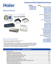
Haier 2U18MS2VHB Service Manual (140 pages)
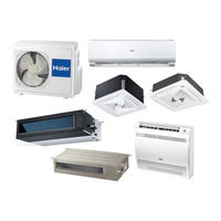
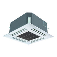
Ductless Multi-Split Heat Pump, Outdoor/Indoor, Wall Mount - Highwall, 2'x2' Compact Cassette, 3'x3' Large Cassette, Slim Duct, Mid-Static Ducted, Medium Static Ducted, Console
Table of Contents
Haier 2U18MS2VHB Technical Overview (122 pages)
Brand: Haier
|
Category: Air Conditioner
|
Size: 39 MB
Table of Contents
Advertisement
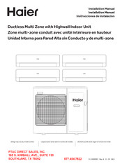
Haier 2U18MS2VHB Installation Manual (56 pages)
Ductless Multi Zone with Highwall Indoor Unit
Table of Contents
Advertisement