Sign In
Upload
Manuals
Brands
Fuji Electric Manuals
Inverter
FRENIC-MEGA
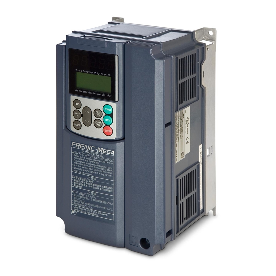
Fuji Electric FRENIC-MEGA Manuals
Manuals and User Guides for Fuji Electric FRENIC-MEGA. We have
3
Fuji Electric FRENIC-MEGA manuals available for free PDF download: Instruction Manual, Starting Manual
Fuji Electric FRENIC-MEGA Instruction Manual (288 pages)
High Performance, Multifunction Inverter
Brand:
Fuji Electric
| Category:
Inverter
| Size: 7 MB
Table of Contents
Instruction Manual
1
Installation
3
Safety Precautions
3
Wiring
4
Operation
5
Disposal
6
General Precautions
6
Maintenance and Inspection, and Parts Replacement
6
Conformity to the Low Voltage Directive in the EU
7
Conformity with UL Standards and CSA Standards (Cul-Listed for Canada)
11
Table of Contents
15
Acceptance Inspection
16
Chapter 1 BEFORE USING the INVERTER
16
External View and Terminal Blocks
17
Precautions for Using Inverters
18
Storage Environment
18
Precautions for Connection of Peripheral Equipment
19
Wiring Precautions
19
Molded Case Circuit Breaker (MCCB) and Residual-Current-Operated Protective Device (Rcd)/Earth Leakage Circuit Breaker (ELCB)
20
Noise Reduction
21
Leakage Current
22
Machine Vibration
22
Precautions in Running Inverters
22
Selecting Inverter Capacity
22
Brake Motors
23
Explosion-Proof Motors
23
Precautions in Using Special Motors
23
Submersible Motors and Pumps
23
Chapter 2 Mounting and Wiring the Inverter
24
Operating Environment
24
Installing the Inverter
24
Clearances
24
Changing the Positions of the Top and Bottom Mounting Bases
25
Screw Size, Count and Tightening Torque
25
For Inverters with a Capacity of 22 Kw or below
26
For Inverters with a Capacity of 30 to 630 Kw
26
Removing and Mounting the Front Cover and the Wiring Guide
26
Arrangement of Main Circuit Terminals
27
Screw Specifications and Recommended Wire Sizes
27
Recommended Wire Sizes
29
Arrangement of Control Circuit Terminals (Common to All Inverter Types)
30
Preparing for the Wiring Guide
30
Wiring Precautions
30
Wiring of Main Circuit Terminals and Grounding Terminals
32
DC Braking Resistor Terminals P (+) and DB (for Inverters with a Capacity of 22 Kw or Below)
35
DC Reactor Terminals P1 and P (+)
35
Inverter Output Terminals U, V, and W and Secondary Grounding Terminals (G) for Motor
35
Primary Grounding Terminal (G) for Inverter Enclosure
35
DC Link Bus Terminals P (+) and N (-)
36
Power Switching Connectors (CN UX) (for 400 V Class Series with 75 Kw or Above)
36
Fan Power Supply Switching Connectors (CN R and CN W) (for 200 V Class Series with 37 Kw or above and 400 V Class Series with 75 Kw or Above)
37
Location of the Switching Connectors
37
Auxiliary Control Power Input Terminals R0 and T0 (for Inverters with a Capacity of 1.5 Kw or Above)
38
Connection Example of Residual-Current-Operated Protective Device (Rcd)/Earth Leakage Circuit Breaker (ELCB)
38
Inserting/Removing the Jumpers
38
Main Circuit Power Input Terminals L1/R, L2/S, and L3/T (Three-Phase Input)
38
Auxiliary Fan Power Input Terminals R1 and T1
39
Connecting/Disconnecting Wires To/From a Control Circuit Terminal
39
Wiring for Control Circuit Terminals
39
Symbols, Names and Functions of the Control Circuit Terminals
40
Setting up the Slide Switches
46
Wiring for Control Circuit Terminals
46
Function of each Slide Switch
47
Location of the Slide Switches on the Control PCB
47
Mounting and Connecting a Keypad
48
Mounting a Keypad on the Panel Wall
48
Removing and Mounting a Keypad
48
LED Monitor, Keys and LED Indicators on the Keypad
49
Overview of Keypad Functions
49
Chapter 3 OPERATION USING the KEYPAD (in the Case of Remote Keypad)
49
Overview of Operation Mode
50
Status Transition between Operation Modes
50
Running Mode
51
Monitoring the Running Status
51
Monitoring Light Alarms
52
How to Check a Light Alarm Factor
52
How to Remove the Current Light Alarm
52
Menus Available in Programming Mode
53
Selecting Menus to Display
54
Keypad Display Mode Selection-Function Code E52
54
Setting up Basic Function Codes Quickly -- Menu #0 "Quick Setup
54
Basic Key Operation
55
Setting up Function Codes -- Menu #1 "Data Setting
55
Checking Changed Function Codes -- Menu #2 "Data Checking
55
Monitoring the Running Status -- Menu #3 "Drive Monitoring
56
"Drive Monitoring" Display Items
57
Displaying Running Status (3_07) and Running Status (3_23)
58
Binary and Hexadecimal Conversion
59
Checking I/O Signal Status -- Menu #4 "I/O Checking
59
I/O Check Items
60
Displaying Control I/O Signal Terminals
61
Segment Display for External Signal Information
61
Segment Display for I/O Signal Status in Hexadecimal
61
Displaying Control I/O Signal Terminals under Communications Control
62
Displaying Control I/O Signal Terminals on Options
62
Reading Maintenance Information -- Menu #5 "Maintenance Information
62
Display Items in "Maintenance Information"
63
Reading Alarm Information -- Menu #6 "Alarm Information
66
Display Items in "Alarm Information"
67
Copying Data -- Menu #7 "Data Copying
68
List of Data Copying Functions
69
Enabling the Disabled Data Protection
70
Disabling the Enabled Data Protection
70
If Data Copying Does Not Work
70
Alarm Mode
71
Displaying the Alarm History
71
Displaying the Status of Inverter at the Time of Alarm
71
Switching to Programming Mode
71
USB Connectivity
72
Running the Motor for a Test
73
Test Run Procedure
73
Checking Prior to Powering on
73
Chapter 4 RUNNING the MOTOR
73
Powering on and Checking
74
Switching between HD, MD and LD Drive Modes
74
Selecting a Desired Motor Drive Control
75
V/F Control with Slip Compensation Inactive
75
V/F Control with Slip Compensation Active
75
V/F Control with Speed Sensor
76
Dynamic Torque Vector Control with Speed Sensor
76
Vector Control Without & with Speed Sensor
76
Performance Comparison for Drive Controls (Summary)
77
Function Code Basic Settings < 1
77
Function Code Basic Settings and Tuning < 2
78
Tuning Procedure
79
Selection of Tuning Type
79
Preparation of Machinery
79
Tuning Errors
79
Function Code Basic Settings and Tuning < 3
80
Tuning (Tune While the Motor Is Rotating under Vector Control)
81
If Tuning While the Motor Is Rotating Cannot be Selected
82
Function Code Basic Settings < 4
83
Function Code Basic Settings and Tuning < 6
84
Running the Inverter for Motor Operation Check
86
Modification of Motor Control Function Code Data
87
Preparation for Practical Operation
88
Special Operations
88
Jogging Operation
88
Remote and Local Modes
88
Run Commands from the Keypad in the Local Mode
89
Switching between Remote and Local Modes
89
External Run/Frequency Command
89
Function Code Tables
90
Changing, Validating, and Saving Function Code Data When the Inverter Is Running
90
Copying Data
90
Using Negative Logic for Programmable I/O Terminals
90
Chapter 5 FUNCTION CODES
90
Drive Control
91
F Codes: Fundamental Functions
92
E Codes: Extension Terminal Functions
94
C Codes: Control Functions of Frequency
98
H Codes: High Performance Functions
99
P Codes: Motor 1 Parameters
99
A Codes: Motor 2 Parameters
102
B Codes: Motor 3 Parameters
104
R Codes: Motor 4 Parameters
105
J Codes: Application Functions 1
107
D Codes: Application Functions 2
108
U Codes: Application Functions 3
109
Y Codes: Link Functions
112
Factory Default According to Shipping Destination
114
Factory Defaults Depending Upon Inverter Capacity
114
Motor Parameters
115
Details of Function Codes
118
Fundamental Functions
118
Adjustable Elements of Frequency Command 1
119
Setting up a Reference Frequency
119
Using Analog Input (F01 = 1 to 3, or 5)
119
Using the Keypad (F01 = 0 (Factory Default) or 8)
119
Gain and Bias
120
Specifying the Initial Value for the Up/Down Control
121
Using Digital Input Signals Up/Down (F01 = 7)
121
Initial Frequency for the Up/Down Control When the Frequency Command Source Is Switched
122
Selecting the Pulse Train Input Format (D59)
122
Using Pulse Train Input (F01 = 12)
122
Pulse Count Factor 1 (D62), Pulse Count Factor 2 (D63)
123
3-Wire Operation with External Input Signals (Digital Input Terminal Commands)
124
Filter Time Constant (D61)
124
Operation Method
124
Switching Frequency Command
124
Base Frequency 1, Rated Voltage at Base Frequency 1 Maximum Output Voltage 1
125
Maximum Frequency 1
125
Base Frequency 1 (F04)
126
Normal (Linear) V/F Pattern
126
Rated Voltage at Base Frequency 1 (F05)
126
V/F Pattern with Three Non-Linear Points
126
Maximum Output Voltage 1 (F06)
127
Non-Linear V/F Patterns 1, 2 and 3 for Frequency (H50, H52 and H65)
127
Non-Linear V/F Patterns 1, 2 and 3 for Voltage (H51, H53 and H66)
127
Acceleration/Deceleration Pattern (H07)
128
Acceleration/Deceleration Time
128
S-Curve Acceleration/Deceleration
128
Curvilinear Acceleration/Deceleration
129
F10 to F12 Electronic Thermal Overload Protection for Motor 1
130
Select Motor Characteristics (F10)
130
Example of Operating Characteristics
131
Overload Detection Level (F11)
131
Thermal Time Constant (F12)
131
Restart Mode after Momentary Power Failure (Mode Selection) (F14)
132
Under V/F Control
132
Under Vector Control with Speed Sensor
133
Under Vector Control Without Speed Sensor
133
Restart Mode after Momentary Power Failure (Basic Operation with Auto Search Disabled)
134
Restart Mode after Momentary Power Failure (Allowable Momentary Power Failure Time) (H16)
135
Restart Mode after Momentary Power Failure (Basic Operation with Auto Search Enabled)
135
Restart Mode after Momentary Power Failure (Restart Time) (H13)
136
Continue to Run
137
Restart after Momentary Power Failure (Continuous Running Level) (H15)
137
Restart Mode after Momentary Power Failure (Frequency Fall Rate) (H14)
137
Trip after Decelerate-To-Stop
137
Bias (Frequency Command 1)
138
DC Braking 1 (Braking Starting Frequency, Braking Level, and Braking Time); DC Braking (Braking Response Mode)
138
Frequency Limiter (High and Low) (F15, F16)
138
Low Limiter (Mode Selection) (H63)
138
Braking Response Mode (H95)
139
Starting Frequency 1 (F23)
140
Starting Frequency 1 (Holding Time) (F24)
140
Stop Frequency (Holding Time) (F39)
140
Under Vector Control Without/With Speed Sensor
140
Stop Frequency (Detection Mode) (F38) (under Vector Control with Speed Sensor)
141
Stop Frequency (F25)
141
Zero Speed Control (D24)
141
Motor Sound (Carrier Frequency) (F26)
142
Motor Sound (Tone) (F27)
142
Function (F31 and F35)
143
Mode Selection (F29 and F32)
143
Voltage Adjustment (F30 and F34)
143
Load Selection/Auto Torque Boost/Auto Energy Saving Operation 1
144
V/F Characteristics
144
Auto Energy Saving Operation (H67)
145
Auto Torque Boost
145
Manual Torque Boost (F09)
145
Torque Boost
145
Related Function Codes
146
Torque Limit Control Mode
146
Analog Torque Limit Values (E61 to E63)
147
Switching Torque Limiters
147
Torque Limiter 1-1, 1-2, 2-1 and 2-2 (F40, F41, E16 and E17)
147
Torque Limiter Levels Specified Via Communications Link (S10, S11)
147
Torque Limiter (Control Target) (H74)
148
Torque Limiter (Frequency Increment Limit for Braking) (H76)
148
Torque Limiter (Operating Conditions) (H73)
148
Torque Limiter (Target Quadrants) (H75)
149
F42 Specifies the Motor Drive Control
151
Dynamic Torque Vector Control
152
Vector Control with Speed Sensor
152
Vector Control Without Speed Sensor
152
Instantaneous Overcurrent Limiting (Mode Selection) (H12)
153
Level (F44)
153
Mode Selection (F43)
153
Allowable Average Loss (F51)
154
Calculating the Discharging Capability and Allowable Average Loss of the Braking Resistor and Configuring the Function Code Data
154
Discharging Capability (F50)
154
Resistance (F52)
154
E Codes (Extension Terminal Functions)
156
E01 to E07 Terminal (X1) to (X7) Function
156
Enable External Alarm Trip-THR (Function Code Data=9)
158
Reset Alarm-RST (Function Code Data=8)
158
Switch to Commercial Power for 50 Hz or 60 Hz-SW50 and SW60 (Function Code Data=15 and 16)
158
Terminal Function Assignment and Data Setting
158
Operation Schemes
159
Example of Sequence Circuit
160
Cancel PID Control-Hz/Pid (Function Code Data=20)
161
Example of Operation Time Scheme
161
Switch Normal/Inverse Operation-IVS (Function Code Data=21)
161
Force to Stop-Stop (Function Code Data=30)
162
Hold PID Integral Component-PID-HLD (Function Code Data=34)
162
Universal DI-U-DI (Function Code Data=25)
162
When the Process Control Is Performed by the PID Processor Integrated in the Inverter
162
Circuit Diagram and Configuration
163
Enable Integrated Sequence to Switch to Commercial Power (50 Hz) and (60 Hz)-ISW50 and ISW60(Function Code Data=40 and 41)
163
Selection of Commercial Power Switching Sequence
164
Timing Scheme
164
Examples of Sequence Circuits
165
Sequence with an Emergency Switching Function
165
Standard Sequence
165
Cancel PG Alarm-PG-CCL (Function Code Data=77)
166
Run Forward-FWD (Function Code Data=98)
166
Sequence with an Emergency Switching Function-Part 2 (Automatic Switching by the Alarm Output Issued by the Inverter)
166
Inverter Running-Run (Function Code Data=0)
168
Torque Polarity Detected-B/D (Function Code Data=4)
168
Undervoltage Detected (Inverter Stopped)-LU (Function Code Data=3)
168
Inverter Output Limiting-IOL (Function Code Data=5)
169
Inverter Ready to Run-RDY (Function Code Data=10)
169
Select AX Terminal Function-AX (Function Code Data=15)
169
Universal DO-U-DO (Function Code Data=27)
169
Braking Transistor Broken-DBAL (Function Code Data=105)
170
Speed Valid-DNZS (Function Code Data=70)
170
Terminal (C1) Wire Break-C1OFF (Function Code Data=59)
170
Under PID Control-PID-CTL (Function Code Data=43)
170
Current Detected, Current Detected 2 and Current Detected 3-ID, ID2 and ID3
172
Low Current Detected-IDL
172
Motor Overload Early Warning Signal-OL
172
Display Coefficients for PID Process Command and Its Feedback (J01=1 or 2)
173
Display Coefficient for Analog Input Monitor
174
Display Coefficients for PID Dancer Position Command and Its Feedback (J01=3)
174
LED Display Filter
174
LED Monitor (Item Selection)
175
LCD Monitor (Item Selection)
176
LED Monitor (Display When Stopped)
176
Keypad (Menu Display Mode)
177
LCD Monitor (Contrast Control)
177
LCD Monitor (Language Selection)
177
LED Monitor (Speed Monitor Item)
177
E61 to E63 Terminal (12) Extended Function
179
Reference Loss Detection (Continuous Running Frequency)
179
Saving of Digital Reference Frequency
179
C Codes (Control Functions)
181
P Codes (Motor 1 Parameters)
184
H Codes (High Performance Functions)
185
A Codes (Motor 2 Parameters)
185
B Codes (Motor 3 Parameters)
185
R Codes (Motor 4 Parameters)
185
J Codes (Application Functions 1)
209
D Codes (Application Functions 2)
222
U Codes (Application Functions 3)
228
Y Codes (Link Functions)
236
Chapter 6 TROUBLESHOOTING
239
Protective Functions
239
Before Proceeding with Troubleshooting
241
Indication ( L-Al ) Appears on the LED Monitor
241
Abnormal Motor Operation
242
Problems with Inverter Settings
247
If an Alarm Code Appears on the LED Monitor
248
If the "Light Alarm" Indication
259
If an Abnormal Pattern Appears on the LED Monitor
260
Is Displayed
260
Chapter 7 MAINTENANCE and INSPECTION
261
Daily Inspection
261
Periodic Inspection
261
List of Periodic Replacement Parts
262
Judgment on Service Life
263
Measurement of Electrical Amounts in Main Circuit
265
Insulation Test
266
Inquiries about Product and Guarantee
267
When Making an Inquiry
267
Product Warranty
267
Chapter 8 SPECIFICATIONS
269
Standard Model 1 (Basic Type)
269
Three-Phase 200 V Class Series
269
Three-Phase 400 V Class Series
270
Standard Model 2 (EMC Filter Built-In Type)
273
Three-Phase 200 V Class Series
273
Three-Phase 400 V Class Series
274
Common Specifications
277
External Dimensions
279
Standard Models
279
DC Reactor
279
Chapter 9 CONFORMITY with STANDARDS
281
Compliance with UL Standards and Canadian Standards (Cul Certification)
281
General
281
Considerations When Using FRENIC-MEGA in Systems to be Certified by UL and Cul
281
Compliance with European Standards
281
Compliance with EMC Standards
281
Recommended Installation Procedure
282
Leakage Current of EMC-Filter Built-In Type of Inverters
283
Harmonic Component Regulation in the EU
284
General Comments
284
Compliance with the Harmonic Component Regulation
284
Compliance with the Low Voltage Directive in the EU
284
General
284
Points for Consideration When Using the FRENIC-MEGA Series in a System to be Certified by the Low Voltage Directive in the EU
284
Compliance with EN954-1, Category 3
285
General
285
En954-1
285
Notes
286
Advertisement
Fuji Electric FRENIC-MEGA Instruction Manual (358 pages)
High Performance, Multifunction Inverter
Brand:
Fuji Electric
| Category:
Inverter
| Size: 6 MB
Table of Contents
Safety Precautions
3
Conformity to the Low Voltage Directive in the EU
7
Conformity with UL Standards and CSA Standards (Cul-Listed for Canada)
11
Table of Contents
19
Chapter 1 BEFORE USING the INVERTER
21
Acceptance Inspection
21
External View and Terminal Blocks
22
Precautions for Using Inverters
24
Precautions in Introducing Inverters
24
Precautions in Running Inverters
29
Precautions in Using Special Motors
29
Precautions for Use on Single-Phase Power
30
Chapter 2 MOUNTING and WIRING the INVERTER
31
Operating Environment
31
Installing the Inverter
31
Wiring
34
Removing and Mounting the Front Cover and the Wiring Guide
34
Screw Specifications and Recommended Wire Sizes
35
Wiring Precautions
38
Wiring of Main Circuit Terminals and Grounding Terminals
41
Wiring for Control Circuit Terminals
48
Setting up the Slide Switches
55
Mounting and Connecting the Keypad
57
Chapter 3 OPERATION USING the KEYPAD
58
LED Monitor, LCD Monitor, and Keys
58
Overview of Operation Modes
60
Running Mode
61
Running or Stopping the Motor
61
Monitoring the Running Status on the LED Monitor
62
Monitoring Light Alarms
64
Programming Mode
65
Setting up Function Codes Quickly Using Quick Setup -- Menu #0 "Quick Setup
66
Setting up Function Codes -- Menu #1 "Data Setting
66
Checking Changed Function Codes -- Menu #2 "Data Checking
69
Monitoring the Running Status -- Menu #3 "Drive Monitoring
69
Checking I/O Signal Status -- Menu #4 "I/O Checking
72
Reading Maintenance Information -- Menu #5 "Maintenance Information
75
Reading Alarm Information -- Menu #6 "Alarm Information
81
Viewing Causes of Alarm -- Menu #7 "Alarm Cause
84
Data Copying -- Menu #8 "Data Copying
86
Measuring Load Factor -- Menu #9 "Load Factor Measurement
93
Changing Function Codes Covered by Quick Setup -- Menu #10 "User Setting
96
Helping Debugging for Communication -- Menu #11 "Communication Debugging
97
Alarm Mode
98
Chapter 4 RUNNING the MOTOR
100
Running the Motor for a Test
100
Test Run Procedure
100
Checking Prior to Powering on
100
Powering on and Checking
101
Switching between LD, MD and HD Drive Modes
101
Selecting a Desired Motor Drive Control
102
Function Code Basic Settings < 1
105
Function Code Basic Settings and Tuning < 2
106
Function Code Basic Settings and Tuning < 3
108
Function Code Basic Settings < 4
112
Function Code Basic Settings and Tuning < 5
113
Running the Inverter for Motor Operation Check
115
Preparation for Practical Operation
117
Special Operations
118
Jogging (Inching) the Motor
118
Remote and Local Modes
118
External Run/Frequency Command
119
Chapter 5 FUNCTION CODES
120
Function Code Tables
120
Details of Function Codes
153
Fundamental Functions
153
E Codes (Extension Terminal Functions)
198
C Codes (Control Functions)
226
P Codes (Motor 1 Parameters)
230
H Codes (High Performance Functions)
235
A Codes (Motor 2 Parameters)
235
B Codes (Motor 3 Parameters)
235
R Codes (Motor 4 Parameters)
235
J Codes (Application Functions 1)
235
D Codes (Application Functions 2)
278
U Codes (Application Functions 3)
286
Y Codes (Link Functions)
295
Chapter 6 TROUBLESHOOTING
299
Protective Functions
299
Before Proceeding with Troubleshooting
302
If Neither an Alarm Code nor "Light Alarm" Indication ( L-Al ) Appears on the LED Monitor
302
Abnormal Motor Operation
303
Problems with Inverter Settings
309
If an Alarm Code Appears on the LED Monitor
310
If the "Light Alarm" Indication ( L-Al ) Appears on the LED Monitor
323
If an Abnormal Pattern Appears on the LED Monitor Except Alarm Codes and "Light Alarm" Indication ( L-Al )
324
If the Inverter Is Running on Single-Phase Power
325
Chapter 7 MAINTENANCE and INSPECTION
326
Daily Inspection
326
Periodic Inspection
326
List of Periodic Replacement Parts
328
Judgment on Service Life
328
Measurement of Electrical Amounts in Main Circuit
331
Insulation Test
332
Inquiries about Product and Guarantee
332
When Making an Inquiry
332
Product Warranty
333
Chapter 8 SPECIFICATIONS
335
Standard Model 1 (Basic Type)
335
Three-Phase 230 V Series
335
Three-Phase 460 V Series
336
Standard Model 2 (DCR Built-In Type)
339
Three-Phase 230 V Series
339
Three-Phase 460 V Series
340
Common Specifications
341
External Dimensions
344
Standard Models
344
Panel Cutting of Standard Model (50 HP or Above)
345
DC Reactor (DCR)
346
DCR Built-In Type
349
Standard Models with NAMA1 Kit (Option)
350
Keypad (TP-G1W-J1)
351
Chapter 9 CONFORMITY with STANDARDS
352
Compliance with UL Standards and Canadian Standards (Cul Certification)
352
General
352
Considerations When Using FRENIC-MEGA in Systems to be Certified by UL and Cul
352
Compliance with European Standards
352
Compliance with EMC Standards
352
Recommended Installation Procedure
353
Compliance with EN954-1, Category 3
354
General
354
Notes for Compliance to En954-1 Category 3
354
En954-1
355
Fuji Electric FRENIC-MEGA Starting Manual (44 pages)
High Performance Multifunction Inverter
Brand:
Fuji Electric
| Category:
Inverter
| Size: 2 MB
Table of Contents
Table of Contents
3
Safety Information and Conformity to Standards
5
Mounting the Inverter
8
Wiring the Inverter
10
Operation Using the Keypad
21
Quick Start Commissioning
23
Function Codes
30
Troubleshooting
40
Specifications and External Dimensions
41
Options
43
Advertisement
Advertisement
Related Products
Fuji Electric FRENIC-Multi
Fuji Electric Frenic-Mini
Fuji Electric Frenic Mega Series
Fuji Electric frenic mini series
Fuji Electric FRENIC-Multi Series
Fuji Electric FRENIC-Ace series
Fuji Electric FRENIC5000G11S Series
Fuji Electric FRENIC-HVAC series
Fuji Electric Frenic Eco Series
Fuji Electric FRENIC5000 P5 Series
Fuji Electric Categories
Air Conditioner
Inverter
Measuring Instruments
Controller
Control Unit
More Fuji Electric Manuals
Login
Sign In
OR
Sign in with Facebook
Sign in with Google
Upload manual
Upload from disk
Upload from URL