Sign In
Upload
Manuals
Brands
Fresenius Medical Care Manuals
Medical Equipment
4008 S
User Manuals: Fresenius Medical Care 4008 S Device
Manuals and User Guides for Fresenius Medical Care 4008 S Device. We have
2
Fresenius Medical Care 4008 S Device manuals available for free PDF download: Technical Manual, Service Manual
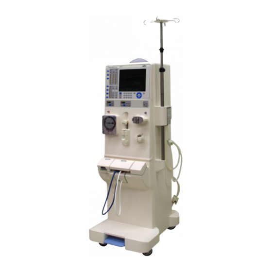
Fresenius Medical Care 4008 S Service Manual (408 pages)
Hemodialysis device
Brand:
Fresenius Medical Care
| Category:
Medical Equipment
| Size: 17 MB
Table of Contents
Table of Contents
3
Significance of the Note
14
Precautions for Working on the Device
14
Technical Documentation
15
Warnings
15
Warnings Relating to Hygiene
15
Warnings Relating to Electricity
15
Addresses
16
3 Installation
17
Important Initial Start-Up Information
17
Important Information for Use in a Domestic Environment
18
Initial Start-Up Report
18
Explanations for the Initial Start-Up Report
22
Transportation of Hemodialysis Unit
44
4 Specifications
47
Dimensions and Weight
47
Type Label (Identification of the Device)
48
Operating Environment
49
Electrical Safety
49
Electrical Supply
50
Fuses
50
Supply Mains
51
Guidance and Manufacturer's Declaration for EMC (IEC 60601-1-2)
54
Electromagnetic Emissions
54
Electromagnetic Immunity
54
Recommended Separation Distances between Portable and Mobile RF
56
Telecommunication Devices and the Device
56
Operating Conditions
57
Consumption Data / Energy Data
58
Storage Conditions
59
External Connection Options
59
Override Conditions
60
Materials Used
61
5 Setup / Service Program
67
Service Mode
67
Service Mode Overview
67
Service Mode Key Functions
68
Setup Menu
69
SETUP MENU - Menu Structure
69
Part 1: Setting Alarm and Warning Times
70
Part 2: Setting the Cleaning Program
72
Part 3: Mixing Ratio
77
Part 4: Setting the Conductivity Limit
81
Part 5: Cleaning Program Info Sound
81
Part 6: Setting Dialysis Parameters
81
Part 7: Cumulated Blood Volume
85
Part 8: OCM Settings
85
Part 9: Automatically Starting Single-Needle Mode
86
Part 10: Activating Monit_Ntc 109
87
Part 11: UF Settings
87
Part 12: Setting the Priming Time
87
Part 13: Sound I/O Switch
88
Part 14: Activating the Key Click
88
Part 15: Setting the BPR/UFR Warning
88
Part 16: Setting the Rinse Volume
89
Part 17: T1 Test Autostart
89
Part 18: Setting the Venous Alarm Window
89
Part 19: Setting Central Delivery
90
Part 20: Autooff after Autoon
90
Part 21: CAMUS Baud Rate
91
Part 22: BPM Settings (Optional)
91
Part 23: Storing Default Values
95
SETUP MENU Settings
95
Diagnostics
98
DIAGNOSTICS, General Information
98
DIAGNOSTICS Menu Structure
100
Reading the Analog Inputs of CPU 1
101
Reading the Analog Inputs of CPU 2
103
Reading the Digital Inputs of CPU 1
104
Reading the Digital Inputs of CPU 2
109
Setting the Analog Outputs of CPU 1
113
Setting the Analog Outputs of CPU 2
114
Setting the Digital Outputs of CPU 1
114
Setting the Digital Outputs of CPU 2
120
Setting / Reading the Digital Outputs of CPU 1
123
Hpu
124
BPM (Option)
125
Miscellaneous
126
MISCELLANEOUS Menu Structure
126
System Clock
127
Sw-Version-Number
128
BPM (Option)
128
Calibration
129
DIP Switch Overview
130
LP 1631 (CPU 1) DIP Switch Array 1
130
LP 1631 (CPU 1) DIP Switch Array 2
131
LP 1631 (CPU 1) DIP Switch Array 3
132
LP 632 (CPU 2) DIP Switch Array 1
134
LP 632 (CPU 2) DIP Switch Array 2
135
LP 634: DIP Switch (Array 1)
136
Software Update
137
Error Code Table
138
Service Program (Quick Guide)
140
6 TSC / Maintenance
143
Important Information for TSC / Maintenance Procedures
143
Accessories and Supplies
144
TSC / MA Test Report
144
Explanations on the Test Report - TSC / MA TSC, Explanations on Test Report
148
Test Report - TSC
174
7 Error Messages
177
T1 Test
177
Prerequisites for Starting and Running the Test
177
Bypass Test
177
Opt. Detector Test
178
Blood System Test
179
Ven. Pressure System Test
181
Air Detector Test
182
Display Test
184
Art. Pressure System Test
184
Battery Test
184
Blood Leak Test
185
Temperature Test
185
Negative Pressure Test (Negative Pressure Holding Test)
186
Positive Pressure Test (Positive Pressure Holding Test)
187
UF Function Test
190
Conductivity Test
191
DIASAFE Plus Test/ HPU Test
192
Device Error During Cleaning Programs
194
V84 Monitoring
194
PSW (Pressure Switch) Monitoring During Free Rinsing (Only with Devices with CDS)
195
Rinse Section Test (Check of V91, V99, V100) (Only Devices with CDS)
198
Rinse Section Test (Check of V91 and V98) (Only Devices Without CDS)
199
Rinse Section Test (Check of V91, V99, V100, V130) (Only Devices Without CDS)
199
V39 Test
201
Further Messages Which May be Displayed before or During a Cleaning Program
201
Error Messages after Turning Power on
204
Error Messages During Treatment
205
HPU (Hydraulic Processing Unit) Error Messages
208
Blood Pump (Arterial) Error Messages
210
Heparin Pump Error Messages
210
BPM Module Error Messages
211
8 Tools (Service Equipment)
215
9 Calibration / Adjustment
221
Calibration
221
Settings Without Menu Display
221
CALIBRATION Menu Structure
222
Part 1: Calibrating the Arterial Pressure
224
Part 2: Calibrating the Pressure in the Arterial Blood Pump
225
Without Menu Display: Setting the Blood Pump Stop Alarm
226
Part 3: Calibrating the Venous Pressure
227
Part 4: Calibrating the Venous Pressure Measurement in the Air Detector
228
Part 5: Calibrating the Blood Pump Rate
229
Part 5.1: Calibrating the Arterial Blood Pump Rate
229
Part 5.2: Calibrating the SN Blood Pump Rate (Option)
230
Without Menu Display: Calibrating the Single-Needle Blood Pump (Single-Needle Pressure) (Optional)
231
Part 6: Measuring the Volume of the UF Pump in Liters
232
Part 7: Calibrating the Degassing Pressure
233
Part 8: Calibrating the 300 Flow Rate
233
Without Menu Display: Adjusting the Current Increasing Pulse
234
(If an Oscilloscope Is Not Available)
234
Part 9: Calibrating the 500 Flow Rate
235
Part 10: Calibrating the 800 Flow Rate
236
Part 11: Calibrating the Dialysate Temperature
236
Part 11.1: Setting the Dialysate Temperature
237
Part 11.2: Check the Dialysate Temperature
238
Part 11.3: Checking the Dialysate Temperature for OCM
239
Part 12: Calibrating the Mixing System
240
Part 12.1: Running in the Membrane Pumps
240
Part 12.2: Determining the Balancing Chamber Volume
241
Part 12.3: Calibrating the Concentrate Pump Stroke
242
Part 12.4: Measuring the Volume of the Concentrate Pump in Liters
243
Part 12.5: Calibrating the Bicarbonate Pump Stroke
244
Part 12.6: Measuring the Volume of the Bicarbonate Pump in Liters
245
Part 12.7: Checking the Concentrate and Bicarbonate Volumes
246
Part 13.1: Conductivity Setting
248
Part 13.2: Temperature/Conductivity Compensation Setting
249
Part 13.3: Calibrating the OCM Pulse
250
Part 13.4: Conductivity Test
251
Part 13.5: Checking the OCM Conductivity
252
Part 13.6: Temperature / Conductivity Compensation Test
253
Part 14: Calibrating the Dialysate Pressure
254
Part 14.1: Dialysate Pressure
255
Part 14.2: TMP-Check
256
Part 14.3: PDIAL2 Press-Check
256
Part 15: Blood Leak Voltage
257
Part 16: Calibrating the Bibag ® Values
258
Part 17: Reset the Failure Record
258
Part 18: Initializing the NOVRAM, Clearing the Mandatory Rinse, Erasing a V84 Malfunction
259
Without Menu Display: Setting the Hall Sensors in the Heparin Pump
259
Hydraulics Unit
262
Reduced Water Inlet Pressure
262
Degassing Pump Pressure
263
Balancing Chamber Loading Pressure
265
Flow Pump Pressure
266
UF Pump Volume
267
CDS (Central Delivery System) Pressure Switch
268
Air Detector
271
Calibration of Air Detector LD 22
271
Adjustment Using the Set for Air Detector Calibration (See Adjustment Instructions)
273
Checking the Venous Occlusion Clamp
274
Calibrating and Checking the Optical Detector
274
Alternative: Adjustment Without the Set for Air Detector Calibration
275
10 Servicing / Repair
277
Precautions for Working on the Hemodialysis Device
277
Equipment
278
Component Overview
279
Monitor
279
Extracorporeal Blood Circuit Module (EBM)
280
Hydraulics Rear
281
Hydraulics, Lateral View from the Left
282
Hydraulics, Lateral View from the Right
283
Hydraulics Legend
284
Assignment of the Hydraulic Processing Unit (HPU)
285
Assembly of Components
286
Self-Cutting Screws
286
Torques
286
Housing and Cart
287
Tilting the Device
287
Brake Rollers
287
Brakes
288
Shunt Interlock
289
Shunt Interlock Complete
289
Microswitch
290
Power Supply Unit and Battery
291
Removing the Power Cable
291
Power Supply Unit
291
Power Board
292
Heater Board
292
Battery
293
Monitor
293
Opening the Monitor
293
Removing and Installing the Printed Circuit Boards
294
LP 630 Motherboard
294
LP 636 External I/O Board
295
Display
295
Removing the Complete Front Panel
295
MDC-II Board and Backlight Inverter
296
TFT Display
297
Backlighting
297
Operation Status Indicator (Traffic Light)
298
Hydraulics Unit
299
Completely Removing the Hydraulic Unit
299
LP 941 HPU with Distribution Bar
300
Heater Block, Heater Rod and Float Switch
301
Heater Block Complete
301
Float Switch
302
Heater Rod
303
Multifunction Block
306
Balancing Chamber
307
Heat Exchanger
307
UF Pump
308
Membrane Pump (Conc/Bic)
309
Gear Pump
310
Pump
310
Motor
310
Blood Leak Detector
311
Valves (Type)
312
Disinfection Valve V84 with CD Monitor
313
Suction Tube
314
1Suction Rod, Rivet, Sealing Plunger
314
Rinse Chamber
315
1Adapter with Rinse Chamber
315
2Reed Switch
315
Bibag Connector
316
1Bibag Connector Complete
316
2Microswitch
317
Filter Holder for DIASAFE ® Plus
317
Extracorporeal Blood Circuit Module (EBM)
318
Opening and Closing the EBM, Service Position
318
Pneumatic Unit Contamination
319
BPM (Option)
320
Luer-Lock Connection Cone
320
Blood Pump
321
Stepper Motor with Gear
321
LP 624 Pump Control
321
Hall Sensor for Rotor
321
Heparin Pump
322
Optical Sensor
322
Drive
323
Mechanics
323
Drip Chamber Holder
324
Drip Chamber Holder Complete
324
Ultrasonic Sensors
324
Compressor / Ventilation Valve
325
Venous Occlusion Clamp with Rotary Magnet, Bolt
326
Calibration and Test Steps after Repair
327
11 Functional Description
331
T1 Test Description
331
T1 Test Flow Diagram, Parallel Run
333
Overview of the Individual Test Sections
334
Blood System Test
337
Venous Pressure System Test
338
10Arterial Pressure System Test
341
16UF Function Test
347
Tests During Cleaning Programs
350
PSW (Pressure Switch) Monitoring During Free Rinsing (Only with Devices with CDS)
350
Rinse Section Test (Check of V91, V99, V100) (Only Devices with CDS)
351
V39 Test
353
Description of the Modules
354
Arterial Blood Pump
354
Single-Needle Blood Pump (Optional)
354
Heparin Pump
355
Air Detector
356
Optical Detector
357
Venous Pressure Measurement
357
Functional Description of the Hydraulic Unit
358
Hydraulic Flow Diagram
358
Description of the Hydraulic Unit
360
Functional Principle of the Balancing Chamber
362
CDS - Central Delivery System (Option)
365
Block Diagrams / Wiring Diagrams / P.C.B. Layouts
373
4008 S Block Diagram
373
Voltage Supply Block Diagram
374
Monitor Block Diagram
375
HPU Block Diagram (Hydraulic Processing Unit)
376
HPU Wiring Diagram (Hydraulic Processing Unit)
377
CAN Communication Connection Diagram
379
LP 450-2 Air Detector Control (LD)
380
LP 493 Blood Leak Detector
382
LP 624 Pump Control, Arterial Blood Pump / Single-Needle Blood Pump (Option)
383
LP 630 Motherboard
384
LP 633-5 Input Board
387
LP 634 Output Board
389
LP 636 External I/O Board
391
LP 645 Membrane Pump Optical Sensor
392
LP 763 Multi-Interface Board (COMMCO III)
393
LP 922 Display Board
394
LP 941 HPU (Hydraulic Processing Unit)
395
LP 950 Control Board (HEP)
396
LP 1131 Operation Status Indicator (Traffic Light)
397
LP 1147 BPM (Optional)
398
LP 1627 Display, EBM SN (Optional)
399
LP 1628 Distributor Board
400
LP 1629 EBM Display
401
Heater Board (4008 Power Supply Unit)
404
Power Board (4008 Power Supply Unit)
405
12 Appendix
407
Advertisement
Fresenius Medical Care 4008 S Technical Manual (595 pages)
Hemodialysis Machine
Brand:
Fresenius Medical Care
| Category:
Medical Equipment
| Size: 13 MB
Table of Contents
Table of Contents
6
Section Page
7
1 Description of Machine Functions and Malfunctions
8
Description of the T1 Test
10
T1 Test Flow Diagram, Serial Program Steps
10
T1 Test Flow Diagram, Parallel Program Steps
12
Description of the T1 Test Incl. Error Messages
14
Description of Machine Errors During the Cleaning Programs
60
Error Messages after Turning Power on
77
Error Messages During Dialysis
78
Functional Description of the Modules
85
Blood Pump (Arterial)
85
Blood Pump (Single Needle), Optional
86
Heparin Pump
87
Air Detector
89
Functional Description of the Hydraulic Unit
90
Description of the Hydraulic Unit
92
Theory of Operation of the Balancing Chamber
94
Central Delivery System Option
98
Program Runs During the Cleaning Programs
99
Technical Safety Checks / Technical Measurement Checks / Maintenance
106
For 4008 Hemodialysis Systems and Options
108
Description - Technical Safety Checks and Maintenance
110
Checklist - Technical Safety Checks and Maintenance
120
Notes - Checking the Electrical Safety
124
Technical Measurement Checks and Maintenance Ki
128
For Options of 4008 Hemodialysis Systems
128
Technical Safety Checks and Maintenance for 4008 Hemodialysis Systems and Options
108
Technical Measurement Checks and Maintenance for Options of 4008 Hemodialysis Systems
128
Description - Technical Measurement Checks and Maintenance
130
Checklist - Technical Measurement Checks and Maintenance
132
TSC Checklist
134
Adjustment Instructions/Overview of the Dip Switches in the 4008
136
3 Adjustment Instructions
136
Overview of the DIP Switches in the 4008
136
Plus (Option)
141
Overview of the DIP Switches in the 4008
146
LP 631 (CPU 1) DIP Switch Array
146
LP 631 (CPU 1) DIP Switch Array
147
LP 632 (CPU 2) DIP Switch Array
148
LP 632 (CPU 2) DIP Switch Array
149
Calibration Mode
150
Basic Conditions
150
Messages on the Displays on the UF Monitor (4008 E/B) or on the Screen (4008 H/S)
150
Hydraulics
152
Reduced Water Inlet Pressure
152
Degassing Pump Pressure
154
Balancing Chamber Loading Pressure
156
Flow Pump Pressure
158
UF Pump Volume
160
CDS Pressure Switch
162
Air Detector
164
4 Calibration Program
166
Diagnostics Program
200
General Notes
202
Menu Structure
204
Reading the Analog Inputs of CPU I
206
Reading the Analog Inputs of CPU
208
Reading the Digital Inputs of CPU I
209
Reading the Digital Inputs of CPU
214
Writing the Analog Outputs of CPU I
218
Writing the Analog Outputs of CPU
219
Writing the Digital Outputs of CPU I
220
Writing the Digital Outputs of CPU
226
Writing/Reading the Digital Outputs of CPU I
229
6 Setup Menu
232
Overview
238
Main Menu 4008 E/B Rev. 5.2
240
Main Menu 4008 H/S Rev. 4.3
266
7 Miscellaneous
296
Section Page/Circuit Diagrams and Circuit Descriptions
298
Section Page
298
8 Circuit Diagrams and Circuit Descriptions
298
Block Diagram 4008
302
AC Diagram 4008 E/H
304
AC Diagram 4008 B/S
306
Block Diagram of Voltage Supply
308
Block Diagram of Screen 4008 H/S
310
Connection Layout Diagram
312
Connection Diagram CAN Communication
313
Hydraulics Processor Block Diagram
314
LP 450-2 Level Detector Control (LD)
316
Description
316
LP 450-2 Level Detector Control (LD)
320
P.C.B. LP 493 Blood Leak Detector
328
Description
328
Circuit Diagram and Component Layout Diagram
329
LP 624 Control Board
332
LP 624 Control Board (BP)
332
Description
332
Circuit Diagram and Component Layout Diagram
335
P.C.B. LP 630 Motherboard
342
Lp 631 Cpu 1
350
Description
350
Lp 631 Cpu
350
Circuit Diagram and Component Layout Diagram
359
Lp 632 Cpu
362
Description
362
Circuit Diagram and Component Layout Diagram
367
LP 633 Input Board
382
Description
382
P.C.B. LP 634 Output Board
402
Description
402
P.C.B. LP 635 Display Board
426
Description
426
LP 636 External Connectors
444
P.C.B. LP 638 Power Supply
448
P.C.B. LP 639 Power Logic
456
LP 950 Control Board (HEP)
468
LP 644-4 Display Board (HEP)
476
LP 645 Position Sensor Membrane Pump
480
LP 647 Power Logic a (4008 B/S)
484
LP 649-2 Display Board (4008 B/S)
492
LP 742 Interference Filter
510
LP 743 Power Control 2 (4008 B/S)
514
LP 744 Power Control 1 (4008 B/S)
520
P.C.B. LP 747 Distribution Board
524
LP 748 Display Board (BP)
530
LP 763 Multi Interface Board
534
LP 922 Display Board (4008 S)
542
LP 923 Traffic Light (4008 H/S)
558
LP 924 Display Board (4008 H)
562
P.C.B. LP 941 Hydraulics Processor
578
Advertisement
Related Products
Fresenius Medical Care 460018
Fresenius Medical Care GranuFlo 450385
Fresenius Medical Care 460017
Fresenius Medical Care GranuFlo 450385-03
Fresenius Medical Care GranuFlo 450368-03
Fresenius Medical Care 4008 E
Fresenius Medical Care 4008 B
Fresenius Medical Care 4008 H
Fresenius Medical Care 4008 HDF
Fresenius Medical Care 2008K2
Fresenius Medical Care Categories
Medical Equipment
Water Filtration Systems
Gateway
Indoor Furnishing
More Fresenius Medical Care Manuals
Login
Sign In
OR
Sign in with Facebook
Sign in with Google
Upload manual
Upload from disk
Upload from URL