Fluke 1524-P4-256 Thermometer Readout Manuals
Manuals and User Guides for Fluke 1524-P4-256 Thermometer Readout. We have 2 Fluke 1524-P4-256 Thermometer Readout manuals available for free PDF download: Technical Manual

Fluke 1524-P4-256 Technical Manual (104 pages)
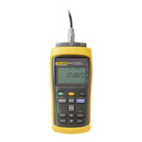
Reference Thermometer
Brand: Fluke
|
Category: Thermometer
|
Size: 5 MB
Table of Contents
Advertisement
Fluke 1524-P4-256 Technical Manual (104 pages)
Reference Thermometer
Brand: Fluke
|
Category: Thermometer
|
Size: 5 MB
Table of Contents
Advertisement