Sign In
Upload
Manuals
Brands
Eaton Manuals
UPS
9E
Eaton 9E Manuals
Manuals and User Guides for Eaton 9E. We have
9
Eaton 9E manuals available for free PDF download: Installation And Operation Manual, Manual, Advanced User's Manual, User Manual
Eaton 9E6Ki, 9E10Ki, 9E10KiXL, 9E15Ki, 9E Series Manual
Brand:
Eaton
| Category:
UPS
| Size: 1 MB
Table of Contents
Introduction
Safety instruction
Special Symbols
Presentation
Model List
Electrical structure
UPS views
UPS FRONT VIEW
UPS REAR VIEW
EBM REAR VIEW
Installation
Unpacking
Package content
Connection
INSTALLATION REQUIREMENTS
UPS WIRING CONNECTION
COMBO VERSION
EBM WIRING CONNECTION
OPERATION
Display and Buttons
Operating UPS
TURNING ON UPS WITH MAINS
TURNING ON UPS WITHOUT MAINS
TURNING OFF UPS WITH MAINS
TURNING OFF UPS WITHOUT MAINS
TRANSFER TO BYPASS
TRANSFER TO MAINTENANCE BYPASS
Configuration
COMMUNICATION PORTS
EATON INTELLIGENT POWER SOFTWARE SUITE
Trouble shooting
Alarm codes
ALARMS
FAULTS
Technical data
Advertisement
Eaton 9E Installation And Operation Manual (114 pages)
20–30 kVA (208/220V)
Brand:
Eaton
| Category:
UPS
| Size: 10 MB
Table of Contents
Table of Contents
5
List of Figures
10
List of Tables
12
1 Introduction
13
Figure 1-1. Eaton 9E UPS (20-30 Kva)
13
UPS Standard Features
14
Installation Features
14
Control Panel
14
Customer Interface
14
High-Efficiency Normal Mode
14
Battery System
14
Advanced Battery Management
14
Options and Accessories
15
External Battery Cabinet Capability
15
External Battery Cabinet
15
Integrated Accessory Cabinet-Distribution
15
Sidecar Integrated Accessory Cabinet-Bypass
15
Integrated Transformer Cabinet
15
Integrated Accessory Cabinet-Tie
15
Integrated Accessory Cabinet-Tie and Bypass
15
Reduced Battery String Model
16
Kva Upgrades
16
1.2.10 Parallel System
16
1.2.11 Monitoring and Communication
16
1.2.12 Dual Feed
16
Basic System Configurations
16
Conventions Used in this Manual
17
Symbols, Controls, and Indicators
17
Using this Manual
17
For more Information
18
Getting Help
18
2 Safety Warnings
19
Section 1 - Installation
21
3 Ups Installation Plan and Unpacking
23
Creating an Installation Plan
23
Preparing the Site
23
Environmental and Installation Considerations
23
Table 3-1. Combined Altitude and Thermal Derating Factors
24
Table 3-2. Air Conditioning or Ventilation Requirements During Full Load Operation
24
Table 3-3. UPS Cabinet Weights
25
Table 3-4. UPS Cabinet Clearances
25
Figure 3-1. UPS Cabinet Dimensions (Front and Right Side Views)
26
Figure 3-2. UPS Cabinet Dimensions (Top and Bottom Views)
27
Figure 3-3. UPS Cabinet Center of Gravity
28
UPS System Power Wiring Preparation
29
Figure 3-4. Remote EPO Switch Dimensions
29
Table 3-5. Input/Output Ratings and External Wiring Requirements for the Eaton 9E-20, 9E-30/20, and 9E-30/30
30
Table 3-6. UPS External Power Cable Terminations for the Eaton 9E-20, 9E-30/20, and 9E-30/30
31
Table 3-7. Power Cable Conduit Requirements
32
Table 3-8. Recommended Input Circuit Breaker Ratings
32
UPS System Interface Wiring Preparation
33
Table 3-9. Recommended Bypass and Output Circuit Breaker Ratings
33
Battery Type
34
Inspecting and Unpacking the UPS Cabinets
34
Table 3-10. Battery Type
34
Figure 3-5. UPS Cabinet as Shipped on Pallet (Wood Container Removed)
36
4 Ups System Installation
37
Preliminary Installation Information
37
Unloading the UPS Cabinet from the Pallet
37
Figure 4-1. Removing the Front Shipping Bracket
38
Figure 4-2. Attaching the Ramp to the Pallet
39
Figure 4-3. Removing the Rear Shipping Bracket
40
Figure 4-4. Rolling the Cabinet down the Ramp
41
Installing Power Terminal Cover Base
42
Figure 4-5. UPS Power Terminal Cover Parts
42
External Battery Cabinet Installation
43
Integrated Transformer Cabinet Installation
43
Figure 4-6. UPS Power Terminal Cover Base Installation and Conduit Landing Wire Entry Locations
43
Integrated Accessory Cabinet-Distribution
44
Integrated Accessory Cabinet-Tie
44
Integrated Accessory Cabinet-Tie and Bypass
44
Sidecar Integrated Accessory Cabinet-Bypass
44
External Power Wiring Installation
44
Figure 4-7. Power Terminal Locations
45
Figure 4-8. Power Terminal Detail
46
Figure 4-9. Power Terminal Cover Top Installation
47
Figure 4-10. Interface Terminal Locations
48
Installing Interface Wiring and Connections
48
Installing Building Alarm Wiring and Connections
48
Figure 4-11. Interface Terminal Detail (Terminal Cover Removed)
49
Figure 4-12. Building Alarm Terminal Block Connector Assignments
49
Table 4-1. Building Alarm Connections
49
Figure 4-13. Interface Terminal Cover
51
Figure 4-14. Interface Conduit Landing and Wiring Channel
52
Figure 4-15. Interface Wiring Access
52
Figure 4-16. Pull Chain Terminal Block Connector Assignments
53
Table 4-2. Pull Chain Connections
53
Installing Parallel Pull Chain and CAN Control Wiring and Connections
53
Installing Mini-Slot Interface Wiring and Connections
54
Figure 4-18. REPO Switch
56
Installing a REPO Switch
56
Figure 4-19. REPO Terminal Block Connector Assignments
57
Table 4-3. REPO Connections
57
Figure 4-20. Normally-Open REPO Switch Wiring
58
Table 4-4. Normally-Open REPO Wire Terminations
58
Table 4-5. Normally-Closed REPO Wire Terminations
58
Figure 4-21. Normally-Closed REPO Switch Wiring
59
Connecting Internal Battery Strings
59
Figure 4-22. Battery Location
60
Figure 4-23. Battery Section
61
Figure 4-24. Battery String Connections
61
Initial Startup
62
Completing the Installation Checklist
62
Figure 5-1. Main Elements of the UPS System
67
Understanding Ups Operation
67
UPS System Overview
67
Single UPS
67
Modes
68
High-Efficiency Normal Mode
68
Standard Normal Mode
68
Figure 5-2. Path of Current through the UPS in Standard Normal Mode
69
Figure 5-3. Path of Current through the UPS in Bypass Mode
70
Figure 5-4. Path of Current through the UPS in Battery Mode
71
Single UPS Unit System Oneline Configurations
72
Figure 5-5. UPS System Oneline - 9E-20 Internal Battery (no External Battery Capability)
73
Figure 5-6. UPS System Oneline - Internal Battery and External Battery Capable
74
Figure 5-7. UPS System Oneline - Internal and External Batteries
75
5 Understanding Ups Operation
76
6 Ups Operating Instructions
77
Figure 6-1. UPS Controls and Indicators
77
Circuit Breakers
78
Control Panel
78
Figure 6-2. UPS Breakers
78
Figure 6-3. UPS Control Panel
79
Using the Control Panel
79
Status Indicators
79
System Events
80
Using the LCD and Pushbuttons
81
MIMIC Screen
82
Table 6-2. Display Function Menu Map
82
Using the Menu
82
Table 6-3. Display Menu Operation
83
System Controls
85
Load off
86
Table 6-4. Command Menu Operation
86
Table 6-5. Typical System Status Messages
86
Single UPS Operation
87
Starting the UPS in High-Efficiency Normal Mode (Default Mode)
87
Starting the Parallel UPS in Bypass Mode
88
Transfer from Bypass to Normal Mode
89
Transfer from HE Normal Mode to Standard Normal Mode
89
Transfer from Normal to Bypass Mode
89
Charger Control
90
Transfer from Standard Normal Mode to HE Normal Mode
90
UPS and Critical Load Shutdown
90
6.3.10 Using the UPS LOAD off Command
91
Battery Test
91
Figure 6-8. REPO Operation
92
Starting the Parallel UPS in High-Efficiency Normal Mode (Default Mode)
93
Transfer from Bypass to Normal Mode
95
Transfer from HE Normal Mode to Standard Normal Mode
95
Transfer from Normal to Bypass Mode
95
Transfer from Standard Normal Mode to HE Normal Mode
96
UPS and Critical Load Shutdown
97
Battery Test
98
Charger Control
98
Using the UPS LOAD off Command
98
6.4.13 Using the Remote Emergency Power-Off Switch
99
7 Communication
101
Mini-Slot Cards
101
Building Alarm Monitoring
101
Figure 7-1. Optional Mini-Slot Cards
101
8 Ups Maintenance
103
Important Safety Instructions
103
Performing Preventive Maintenance
104
DAILY Maintenance
104
MONTHLY Maintenance
104
PERIODIC Maintenance
105
ANNUAL Maintenance
105
BATTERY Maintenance
105
Figure 8-1. Air Filter Location
105
Installing Batteries
106
Recycling the Used Battery or UPS
106
Maintenance Training
106
9 Product Specifications
107
Model Numbers
107
UPS Input
107
UPS Output
108
UPS Environmental
108
UPS Internal Battery Runtimes (in Minutes) at Full Load
108
UPS Internal Battery Plus External Battery Cabinet Runtimes (in Minutes) at Full Load
109
Product Specifications
110
Warranty
111
Eaton 9E Installation And Operation Manual (102 pages)
20–30 kVA (208/220V)
Brand:
Eaton
| Category:
UPS
| Size: 9 MB
Table of Contents
Table of Contents
5
List of Figures
10
List of Tables
12
1 Introduction
13
Figure 1-1. Eaton 9E UPS (20-30 Kva)
13
Options and Accessories
14
External Battery Cabinet
14
Integrated Accessory Cabinet-Distribution
14
Integrated Transformer Cabinet
15
Integrated Accessory Cabinet-Bypass
15
Integrated Accessory Cabinet-Tie
15
Integrated Accessory Cabinet-Tie and Bypass
15
Monitoring and Communication
15
Dual Feed
15
Maintenance Bypass
15
UPS Standard Features
14
Installation Features
14
Control Panel
14
Customer Interface
14
High-Efficiency Normal Mode
14
Advanced Battery Management
14
Battery System
15
Basic System Configurations
16
Conventions Used in this Manual
16
Using this Manual
16
For more Information
17
Symbols, Controls, and Indicators
17
Getting Help
18
2 Safety Warnings
19
Section 1 - Installation
21
3 Ups Installation Plan and Unpacking
23
Creating an Installation Plan
23
Preparing the Site
23
Environmental and Installation Considerations
23
Table 3-1. UPS Cabinet Weights
24
Table 3-2. UPS Cabinet Clearances
24
Table 3-3. Air Conditioning or Ventilation Requirements During Full Load Operation
24
Figure 3-1. UPS Cabinet Dimensions (Front and Right Side Views)
25
Figure 3-2. UPS Cabinet Dimensions (Top and Bottom Views)
26
Figure 3-3. UPS Cabinet Center of Gravity
27
UPS System Power Wiring Preparation
28
Figure 3-4. Remote EPO Switch Dimensions
28
Table 3-4. Input/Output Ratings and External Wiring Requirements for the Eaton 9E-30/20 and 9E-30/30
29
Table 3-5. UPS External Power Cable Terminations for the Eaton 9E-30/20 and 9E-30/30
30
Table 3-6. Power Cable Conduit Requirements
31
Table 3-7. Recommended Input Circuit Breaker Ratings
31
UPS System Interface Wiring Preparation
32
Table 3-8. Recommended Bypass and Output Circuit Breaker Ratings
32
Battery Type
33
Inspecting and Unpacking the UPS Cabinets
33
Table 3-9. Battery Type
33
Figure 3-5. UPS Cabinet as Shipped on Pallet (Wood Container Removed)
35
4 Ups System Installation
37
Preliminary Installation Information
37
Unloading the UPS Cabinet from the Pallet
37
Figure 4-1. Removing the Front Shipping Bracket
38
Figure 4-2. Attaching the Ramp to the Pallet
39
Figure 4-3. Removing the Rear Shipping Bracket
40
Figure 4-4. Rolling the Cabinet down the Ramp
41
Installing Power Terminal Cover Base
42
Figure 4-5. UPS Power Terminal Cover Parts
42
External Battery Cabinet Installation
43
Integrated Transformer Cabinet Installation
43
Figure 4-6. UPS Power Terminal Cover Base Installation and Conduit Landing Wire Entry Locations
43
Integrated Accessory Cabinet-Bypass Installation
44
Integrated Accessory Cabinet-Distribution
44
External Power Wiring Installation
44
Figure 4-7. Power Terminal Locations
45
Figure 4-8. Power Terminal Detail
46
Figure 4-9. Power Terminal Cover Top Installation
47
Installing Interface Connections
48
Installing Building Alarm Connections
48
Figure 4-10. Interface Terminal Locations
48
Figure 4-11. Interface Terminal Detail (Terminal Cover Removed)
49
Figure 4-12. Building Alarm Terminal Block Connector Assignments
49
Table 4-1. Building Alarm Connections
49
Figure 4-13. Interface Terminal Cover
51
Figure 4-14. Interface Conduit Landing and Wiring Channel
52
Figure 4-15. Interface Wiring Access
52
Installing Mini-Slot Interface Connections
53
Installing a REPO Switch
53
Figure 4-16. REPO Switch
54
Figure 4-17. REPO Terminal Block Connector Assignments
54
Table 4-2. REPO Connections
54
Table 4-3. Normally-Open REPO Wire Terminations
55
Figure 4-18. Normally-Open REPO Switch Wiring
56
Figure 4-19. Normally-Closed REPO Switch Wiring
56
Table 4-4. Normally-Closed REPO Wire Terminations
56
Connecting Internal Battery Strings
57
Figure 4-20. Battery Location
58
Figure 4-21. Battery Section
59
Figure 4-22. Battery String Connections
59
Initial Startup
60
Completing the Installation Checklist
60
Installation Checklist
61
Section 2 - Operation
63
5 Understanding Ups Operation
65
UPS System Overview
65
Figure 5-1. Main Elements of the UPS System
65
Single UPS
66
Modes
66
High-Efficiency Normal Mode
66
Standard Normal Mode
66
Figure 5-2. Path of Current through the UPS in Standard Normal Mode
67
Bypass Mode
68
Figure 5-3. Path of Current through the UPS in Bypass Mode
68
Battery Mode
69
Figure 5-4. Path of Current through the UPS in Battery Mode
69
Single UPS Unit System Oneline Configurations
70
Figure 5-5. UPS System Oneline - Internal Battery
71
Figure 5-6. UPS System Oneline - External Battery
72
6 Ups Operating Instructions
73
UPS Controls and Indicators
73
Figure 6-1. UPS Controls and Indicators
73
Circuit Breakers
74
Control Panel
74
Figure 6-2. UPS Breakers
74
Using the Control Panel
75
Status Indicators
75
Figure 6-3. UPS Control Panel
75
Table 6-1. Status Indicators
75
System Events
76
Using the LCD and Pushbuttons
77
Using the Menu
78
MIMIC Screen
78
Table 6-2. Display Function Menu Map
78
Display Menu Operation
79
Table 6-3. Display Menu Operation
79
System Controls
81
Table 6-4. Command Menu Operation
82
Table 6-5. Typical System Status Messages
82
Load off
82
Single UPS Operation
83
Starting the UPS in High-Efficiency Normal Mode (Default Mode)
83
Starting the UPS in Bypass Mode
84
Transfer from Normal to Bypass Mode
85
Transfer from Bypass to Normal Mode
85
Transfer from HE Normal Mode to Standard Normal Mode
85
Transfer from Normal Mode to Maintenance Bypass
85
Transfer from Maintenance Bypass to Normal Mode
85
UPS and Critical Load Shutdown
87
Figure 6-8. Maintenance Bypass Switch
87
6.3.10 Charger Control
88
6.3.11 Battery Test
88
6.3.12 Using the UPS LOAD off Command
88
6.3.13 Using the Remote Emergency Power-Off Switch
89
Figure 6-9. REPO Operation
90
7 Communication
91
Mini-Slot Cards
91
Building Alarm Monitoring
91
Figure 7-1. Optional Mini-Slot Cards
91
8 Ups Maintenance
93
Important Safety Instructions
93
Performing Preventive Maintenance
94
DAILY Maintenance
94
MONTHLY Maintenance
94
PERIODIC Maintenance
95
ANNUAL Maintenance
95
BATTERY Maintenance
95
Figure 8-1. Air Filter Location
95
Installing Batteries
96
Recycling the Used Battery or UPS
96
Maintenance Training
96
9 Product Specifications
97
Model Numbers
97
Specifications
97
UPS Input
97
UPS Output
98
UPS Environmental
98
Warranty
99
Advertisement
Eaton 9E Installation And Operation Manual (114 pages)
40–60 kVA (208/220V) UPS
Brand:
Eaton
| Category:
UPS
| Size: 7 MB
Table of Contents
Table of Contents
5
List of Figures
10
List of Tables
12
1 Introduction
13
Figure 1-1. Eaton 9E UPS (40-60 Kva)
13
Options and Accessories
14
External Battery Cabinet
14
Integrated Accessory Cabinet-Distribution
14
Integrated Transformer Cabinet
15
Integrated Accessory Cabinet-Bypass
15
Integrated Accessory Cabinet-Tie
15
Integrated Accessory Cabinet-Tie and Bypass
15
Parallel System
15
Reduced Battery String Model
15
Monitoring and Communication
16
1.2.10 Dual Feed
16
1.2.11 Maintenance Bypass
16
UPS Standard Features
14
Installation Features
14
Control Panel
14
Customer Interface
14
High-Efficiency Normal Mode
14
Advanced Battery Management
14
Basic System Configurations
16
Battery System
16
Using this Manual
16
Conventions Used in this Manual
17
Symbols, Controls, and Indicators
17
For more Information
18
Getting Help
18
2 Safety Warnings
19
Section 1 - Installation
21
3 Ups Installation Plan and Unpacking
23
Creating an Installation Plan
23
Preparing the Site
23
Environmental and Installation Considerations
23
Table 3-1. UPS Cabinet Weights
24
Table 3-2. UPS Cabinet Clearances
24
Table 3-3. Air Conditioning or Ventilation Requirements During Full Load Operation
24
Figure 3-1. UPS Cabinet Dimensions (Front and Right Side Views)
25
Figure 3-2. UPS Cabinet Dimensions (Top and Bottom Views)
26
Figure 3-3. UPS Cabinet Center of Gravity
27
UPS System Power Wiring Preparation
28
Figure 3-4. Remote EPO Switch Dimensions
28
Table 3-4. Input/Output Ratings and External Wiring Requirements for the Eaton 9E-40, 9E-60/40, and 9E-60/60
29
Table 3-5. UPS External Power Cable Terminations for the Eaton 9E-40, 9E-60/40, and 9E-60/60
30
Table 3-6. Power Cable Conduit Requirements
31
Table 3-7. Recommended Input Circuit Breaker Ratings
31
UPS System Interface Wiring Preparation
32
Table 3-8. Recommended Bypass and Output Circuit Breaker Ratings
32
Battery Type
33
Inspecting and Unpacking the UPS Cabinets
33
Table 3-9. Battery Type
33
Figure 3-5. UPS Cabinet as Shipped on Pallet (Wood Container Removed)
35
4 Ups System Installation
37
Preliminary Installation Information
37
Unloading the UPS Cabinet from the Pallet
37
Figure 4-1. Removing the Front Shipping Bracket
38
Figure 4-2. Attaching the Ramp to the Pallet
39
Figure 4-3. Removing the Rear Shipping Bracket
40
Figure 4-4. Rolling the Cabinet down the Ramp
41
Installing Power Terminal Cover Base
42
Figure 4-5. UPS Power Terminal Cover Parts
42
External Battery Cabinet Installation
43
Integrated Transformer Cabinet Installation
43
Figure 4-6. UPS Power Terminal Cover Base Installation and Conduit Landing Wire Entry Locations
43
Integrated Accessory Cabinet-Bypass Installation
44
Integrated Accessory Cabinet-Distribution
44
Figure 4-7. Power Terminal Locations
46
Figure 4-8. Power Terminal Detail
47
Figure 4-9. Power Terminal Cover Top Installation
48
Figure 4-10. Interface Terminal Locations
49
Installing Interface Connections
49
Installing Building Alarm Connections
49
Figure 4-11. Interface Terminal Detail (Terminal Cover Removed)
50
Figure 4-12. Building Alarm Terminal Block Connector Assignments
50
Table 4-1. Building Alarm Connections
50
Figure 4-13. Interface Terminal Cover
52
Figure 4-14. Interface Conduit Landing and Wiring Channel
53
Figure 4-15. Interface Wiring Access
53
Figure 4-16. Pull Chain Terminal Block Connector Assignments
54
Table 4-2. Pull Chain Connections
54
Figure 4-18. REPO Switch
57
Installing a Repo Switch
57
Figure 4-19. REPO Terminal Block Connector Assignments
58
Table 4-3. REPO Connections
58
Figure 4-20. Normally-Open REPO Switch Wiring
59
Table 4-4. Normally-Open REPO Wire Terminations
59
Table 4-5. Normally-Closed REPO Wire Terminations
59
Figure 4-21. Normally-Closed REPO Switch Wiring
60
Connecting Internal Battery Strings
60
Figure 4-22. Battery Location
61
Figure 4-23. Battery Section
62
Figure 4-24. Battery String Connections
63
Initial Startup
63
Completing the Installation Checklist
63
Figure 5-1. Main Elements of the UPS System
69
Ups System Overview
69
Figure 5-2. Path of Current through the UPS in Standard Normal Mode
71
Figure 5-3. Path of Current through the UPS in Bypass Mode
72
Figure 5-4. Path of Current through the UPS in Battery Mode
73
Single Ups Unit System Oneline Configurations
74
Figure 5-5. UPS System Oneline - Internal Battery
75
Figure 5-6. UPS System Oneline - External Battery
76
Figure 6-1. UPS Controls and Indicators
77
Figure 6-2. UPS Breakers
78
Figure 6-3. UPS Control Panel
79
Using the Control Panel
79
Status Indicators
79
Table 6-2. Display Function Menu Map
82
MIMIC Screen
82
Table 6-3. Display Menu Operation
83
Table 6-4. Command Menu Operation
86
Table 6-5. Typical System Status Messages
86
Load off
86
Single Ups Operation
87
Figure 6-8. Maintenance Bypass Interlock Cover
91
6.3.12 Using the UPS LOAD off Command
92
Figure 6-9. REPO Operation
94
Multiple UPS Parallel Operation
95
Starting the Parallel UPS in High-Efficiency Normal Mode (Default Mode)
95
Starting the Parallel UPS in Bypass Mode
96
Transfer from Normal to Bypass Mode
97
Transfer from Bypass to Normal Mode
97
Transfer from HE Normal Mode to Standard Normal Mode
97
Transfer from Standard Normal Mode to HE Normal Mode
98
Transfer from Normal Mode to Maintenance Bypass
98
Transfer from Maintenance Bypass to Normal Mode
98
Single UPS Shutdown
98
6.4.10 Single UPS Restart
99
6.4.11 UPS and Critical Load Shutdown
99
6.4.12 Charger Control
100
6.4.14 Using the UPS LOAD off Command
101
7 Communication
103
Mini-Slot Cards
103
Building Alarm Monitoring
103
Figure 7-1. Optional Mini-Slot Cards
103
8 Ups Maintenance
105
Important Safety Instructions
105
Performing Preventive Maintenance
106
DAILY Maintenance
106
MONTHLY Maintenance
106
ANNUAL Maintenance
107
BATTERY Maintenance
107
Figure 8-1. Air Filter Location
107
Installing Batteries
108
Recycling the Used Battery or UPS
108
Maintenance Training
108
9 Product Specifications
109
Model Numbers
109
UPS Output
110
UPS Environmental
110
Battery Runtimes (in Minutes) at Full Load
110
Warranty
111
Eaton 9E Installation And Operation Manual (98 pages)
80–200 kVA (380/400/415V)
Brand:
Eaton
| Category:
UPS
| Size: 9 MB
Table of Contents
Table of Contents
5
1 Introduction
13
Figure 1-1. Eaton 9E UPS (80-200Kva)
13
Options and Accessories
14
External Battery Cabinet
14
Tie Cabinet
14
Parallel System
15
Monitoring and Communication
15
Maintenance Bypass
15
UPS Standard Features
14
Installation Features
14
Control Panel
14
Customer Interface
14
High-Efficiency Mode
14
Advanced Battery Management
14
Basic System Configurations
15
Battery System
15
Using this Manual
15
Conventions Used in this Manual
16
For more Information
16
Symbols, Controls, and Indicators
16
Getting Help
17
2 Safety Warnings
19
Section 1-Installation
21
3 Ups Installation Plan and Unpacking
23
Creating an Installation Plan
23
Preparing the Site
23
Environmental and Installation Considerations
23
Table 3-1. UPS Cabinet Weights
24
Table 3-2. UPS Cabinet Clearances
24
Table 3-3. 9E Required Clearance
24
Figure 3-1. UPS Cabinet Dimensions (Front and Right Side Views)
25
Ups Installation Plan and Unpacking
25
Figure 3-2. UPS Cabinet Dimensions (Top and Bottom Views)
26
UPS System Power Wiring Preparation
28
Table 3-4. Air Conditioning or Ventilation Requirements During Full Load Operation
28
Table 3-6. UPS External Power Cable Terminations for the Eaton 9E 80-200Kva
29
Table 3-5.Input/Output Ratings and External Wiring Requirements for the Eaton 9E 80-200Kva
30
Table 3-7. Recommended Input Circuit Breaker Ratings
31
Table 3-8. Recommended Bypass and Output Circuit Breaker Ratings
31
UPS System Interface Wiring Preparation
32
Table 3-9. Recommended DC Input Circuit Breaker Rating
32
Inspecting and Unpacking the UPS Cabinets
33
Figure 3-4. UPS Cabinet as Shipped on Pallet (Wood Container Removed)
34
4 Ups System Installation
35
Preliminary Installation Information
35
Unloading the UPS Cabinet from the Pallet
35
Figure 4-1. Removing the Front Shipping Bracket
36
Figure 4-2. Attaching the Ramp to the Pallet
37
Figure 4-3. Removing the Rear Shipping Bracket
37
External Battery Cabinet Installation
38
Figure 4-4. Rolling the Cabinet down the Ramp
38
External Power Wiring Installation
39
Figure 4-6. Power Terminal Locations
40
Figure 4-7 . Power Terminal Detail
41
Installing Interface Connections
42
Installing Building Alarm Connections
42
Figure 4-9. Interface Terminal Locations
42
Figure 4-10. Interface Terminal Detail (Terminal Cover Removed)
43
Figure 4-11. Building Alarm Terminal Block Connector Assignments
43
Table 4-1. Building Alarm Connections
43
Figure 4-12. Interface Wiring Access
45
Installing Parallel Pull Chain and CAN Control Wiring and Connections
46
Figure 4-13. Pull Chain Terminal Block Connector Assignments
46
Table 4-2. Pull Chain Connections
46
Installing Mini-Slot Interface Connections
47
Figure 4-14. Parallel UPS Control Wiring
48
Figure 4-15. Parallel UPS System Connections
48
Installing a REPO Switch
49
Table 4-3. REPO Connections
49
Figure 4-17. Normally-Open REPO Switch Wiring
50
Initial Startup
51
Completing the Installation Checklist
51
Figure 4-18. Normally-Closed REPO Switch Wiring
51
Section 2-Operation
55
5 Understanding Ups Operation
57
UPS System Overview
57
Figure 5-1. Main Elements of the UPS System
57
Single UPS
58
Modes
58
Standard Normal Mode
58
High-Efficiency Mode
59
Figure 5-2. Path of Current through the UPS in Standard Normal Mode
59
Bypass Mode
60
Battery Mode
61
Single UPS Unit System Oneline Configurations
62
Understanding Ups Operation
64
6 Ups Operating Instructions
65
UPS Controls and Indicators
65
Figure 6-1. UPS Controls and Indicators
65
Control Panel
66
Figure 6-2. UPS Switches
66
Using the Control Panel
67
Status Indicators
67
Figure 6-3. UPS Control Panel
67
Table 6-1. Status Indicators
67
System Events
68
Using the LCD and Pushbuttons
69
Figure 6-4. Parts of the LCD
69
Using the Menu
70
MIMIC Screen
70
Figure 6-5. Main Menu and MIMIC Screen
70
Table 6-2. Display Function Menu Map
70
Display Menu Operation
71
Table 6-3. Display Menu Operation
71
System Controls
73
Figure 6-6. Typical Initial Setup Screen
73
Figure 6-7. Typical System Control Screen
74
Table 6-4. Command Menu Operation
74
Table 6-5. Typical System Status Messages
74
Single UPS Operation
75
Starting the UPS in Standard Normal Mode (Default Mode)
75
Starting the UPS in Bypass Mode
75
Transfer from Normal to Bypass Mode
76
Transfer from Bypass to Normal Mode
77
Transfer from Standard Normal Mode to HE Mode
77
Transfer from HE Mode to Standard Normal Mode
77
Transfer from Normal Mode to Internal Maintenance Bypass (Optional on 80-120Kva)
77
Transfer from Internal Maintenance Bypass to Normal Mode (Optional on 80-120Kva)
78
UPS and Critical Load Shutdown
78
Figure 6-8. 80-120Kva Optional Internal Maintenance Bypass Switch Arrangement
78
Charger Control
79
Battery Test
79
Using the UPS LOAD off Command
79
Using the Remote Emergency Power-Off Switch
80
Multiple UPS Parallel Operation
81
Starting the Parallel UPS in Standard Normal Mode (Default Mode)
81
Starting the Parallel UPS in Bypass Mode
82
Transfer from Normal to Bypass Mode
82
Transfer from Bypass to Normal Mode
83
Single UPS Shutdown
83
Single UPS Restart
84
UPS and Critical Load Shutdown
84
Charger Control
85
Battery Test
85
Using the UPS LOAD off Command
86
Using the Remote Emergency Power-Off Switch
87
7 Communication
89
Mini-Slot Cards
89
Building Alarm Monitoring
89
Figure 7-1. Optional Mini-Slot Cards
89
8 Ups Maintenance
91
Important Safety Instructions
91
Performing Preventative Maintenance
92
DAILY Maintenance
92
MONTHLY Maintenance
92
ANNUAL Maintenance
93
BATTERY Maintenance
93
Figure 8-1. Air Filter Location
93
Installing Batteries
94
Recycling the Used Battery or UPS
94
Maintenance Training
94
9 Product Specifications
95
Model Numbers
95
Specifications
95
UPS Input
95
UPS Output
96
UPS Environmental
96
Eaton 9E Advanced User's Manual (30 pages)
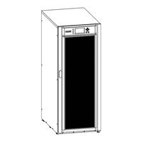
9E Rack
Brand:
Eaton
| Category:
Racks & Stands
| Size: 3 MB
Table of Contents
Table of Contents
2
Special Symbols
4
Introduction
5
Environmental Protection
5
Benefits
6
Presentation
7
Weights and Dimensions
7
Standard Installation
8
Rear Panel
8
Optional Accessories
8
Installation
9
Inspecting the Equipment
9
Recommended Positions
10
EBM Connection
11
UPS Connection
12
Register Warranty
12
Interfaces and Communication
12
Control Panel
12
LCD Description
13
Display Functions
14
User Settings
15
Communication Ports
18
UPS Remote Control Functions
19
Eaton Intelligent Power Software Suite
20
Cybersecurity
20
Operation
20
Start-Up and Normal Operation
20
Starting the UPS on Battery
20
UPS Shutdown
20
Operating Modes
20
Return of AC Input Power
21
Configuring Battery Settings
21
Setting High Efficiency Mode
22
UPS Maintenance
22
Equipment Care
22
Storing the Equipment
22
When to Replace Batteries
22
Replacing Batteries
23
Recycling the Used Equipment
24
Troubleshooting
25
Typical Alarms and Faults
25
Service and Support
27
Specification and Technical Characteristics
27
Electrical Input
27
Electrical Output
28
Battery
29
Environmental and Safety
29
Glossary
30
Eaton 9E Manual (41 pages)
Brand:
Eaton
| Category:
UPS
| Size: 1 MB
Table of Contents
Table of Contents
3
Introduction
4
Safety Instruction
4
Certification Standards
6
Special Symbols
7
Presentation
8
Model List
8
Electrical Structure
8
UPS Views
10
Installation
15
Unpacking
15
Package Content
16
Connection
16
Operation
27
Display and Buttons
27
Operating UPS
31
Configuration
33
Trouble Shooting
35
Alarm Codes
37
Technical Data
38
Eaton 9E Manual (39 pages)
Brand:
Eaton
| Category:
UPS
| Size: 1 MB
Table of Contents
Table of Contents
2
Introduction
3
Safety Instruction
3
Certification Standards
5
Special Symbols
6
Presentation
7
Model List
7
Electrical Structure
7
UPS Views
9
Installation
14
Unpacking
14
Package Content
15
Connection
15
Operation
26
Display and Buttons
26
Operating UPS
30
Configuration
32
Trouble Shooting
34
Alarm Codes
35
Technical Data
37
Eaton 9E Manual (22 pages)
Brand:
Eaton
| Category:
UPS
| Size: 1 MB
Table of Contents
Table of Contents
2
Introduction
3
Safety Instruction
3
Certification Standards
4
Special Symbols
4
Presentation
5
Model List
5
Electrical Structure
5
Ups Views
6
Installation
9
Unpacking
9
Package Content
9
Connection
10
Operation
16
Display and Buttons
16
Operating Ups
18
Configuration
19
Trouble Shooting
20
Alarm Codes
21
Technical Data
22
Advertisement
Related Products
Eaton 9E10Ki
Eaton 9E6Ki
Eaton 9E10KiXL
Eaton 9E15Ki
Eaton 9E20Ki
Eaton 9E20KiXL
Eaton 9EEBM180
Eaton 9EEBM240
Eaton 9E G3
Eaton 9EHD-33-40/20
Eaton Categories
UPS
Circuit breakers
Switch
Industrial Equipment
Industrial Electrical
More Eaton Manuals
Login
Sign In
OR
Sign in with Facebook
Sign in with Google
Upload manual
Upload from disk
Upload from URL