Sign In
Upload
Manuals
Brands
Digi Manuals
Control Unit
ConnectCore
Digi ConnectCore Linux SOM Platform Manuals
Manuals and User Guides for Digi ConnectCore Linux SOM Platform. We have
2
Digi ConnectCore Linux SOM Platform manuals available for free PDF download: Hardware Reference Manual
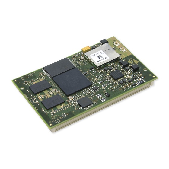
Digi ConnectCore Hardware Reference Manual (151 pages)
For i.MX51
Brand:
Digi
| Category:
Single board computers
| Size: 13.31 MB
Table of Contents
Table of Contents
3
Chapter 1: About the Module
9
Features and Functionality
10
Module Variant
11
Block Diagram
12
Cpu
12
Module
13
Module Pinout
14
Pinout Legend
14
J1 Pinout
14
J2 Pinout
22
Power
31
Module Power Supplies
31
Supply Inputs
31
Supply Outputs
32
MC13892 Power Management
33
Memory
34
DDR2 SDRAM Memory
34
NAND Flash Memory
34
Chip Selects
34
Chip Select Memory Map
34
Multiplexed GPIO
35
GPIO Multiplexing Table
35
Interfaces
40
1-Wire
40
Accelerometer
40
ADC and Touch Screen
40
Synchronous Serial Interface (SSI)
41
External Memory Interface (EMI)
42
Ethernet 1
42
Ethernet 2
42
Video Subsystem
44
Video Processing Unit (VPU)
44
Image Processing Unit (IPU)
46
Keypad
48
Memory Cards
48
Pwm
49
Rtc
50
Spdif
50
Spi
51
Watchdog Timer
51
Uart
52
USB Host and USB OTG
52
Wlan
53
Cable Specification: U.FL/W.FL to RP-SMA
54
Chapter 2: About the Development Board
55
What's on the Development Board
55
The Development Board
57
Switches and Push-Buttons
58
Power Switch, S2
58
Reset Button, S4
59
Power Button, S11
59
User Buttons, S3 and S5
59
Ident Button, S10
59
Legend for Multi-Position Switches
59
UART 1 Switch, S6
60
UART 2 Switch, S7
60
Boot Configuration Switches, S8 and S9
61
Jumpers
62
Battery Enable, J5
62
Module Power Source, P29
63
Led 1, J16
63
Led 2, J9
63
Button 1, J28
63
Button 2, J29
63
UART3 / Xbee Selection, J30 and J31
63
WLAN Disable, J17
63
Touch Selection, J20
63
Coincell Enable, J3
64
JTAG Mod., J4
64
Leds
65
Wlan, Le12
65
Wlan, Le12
66
Power Leds, LE3, LE4, LE6 and LE7
66
User Leds, LE49 and LE51
66
Serial Status Leds
66
UART 1 Status Leds
67
UART 2 Status Leds
67
Xbee Assoc., LE50
67
Audio Interface
68
Line-Out Connector Pinout, J18
69
Line-In Connector Pinout, J12
69
Microphone Connector Pinou, J15
69
Coin Cell Battery
70
Camera Interfaces
71
X15 Pinout
72
X17 Pinout
72
Digital IO Interface
73
Digital I/O Connector, X45
74
Ethernet 1 Interface
75
Ethernet 1, RJ-45 Connector X7
76
Ethernet 2 Interface
77
Ethernet 2, Connector J17
78
HDMI Interface
79
HDMI Connector, J19
80
I 2 C Interface
81
I 2 C Header, P22
82
JTAG Interface
83
Standard JTAG ARM Connector, X13
84
LCD Interfaces
85
LCD 1 Connector, P1
86
P1 Pinout
86
LCD 2 Connector, P2
88
P2 Pinout
88
Microsd™ Card Interface
90
Microsd™ Connector, X14
91
Module Connectors and Signal Rails
92
Module Connectors
93
Signal Rails, J25 and J26
93
J25 Pinout
93
J26 Pinout
96
Peripheral Application Header
99
Peripheral Application Header, P21
100
Power-Over-Ethernet (Poe) - Ieee802.3Af
102
The Poe Module
103
Poe Connector (Power In), P17
103
Poe Connector (Power Out), P18
104
Main Power Connector
105
SD-Card Interface
106
SD/MMC Connector, X18
107
SPI Interface
108
SPI Header, P24
109
UART Interface
110
Serial Port 2, RS232, X27
110
Serial Port 1, MEI Interface, X30
111
Serial Port 3, TTL Interface, X19
112
USB Host Interface
113
USB Host Connectors, J8 and J10
113
USB OTG Interface
114
USB OTG Connector, J11
114
User Interface
115
Analog Video Interface
117
Analog Video Connector, X32
118
WLAN Interface
119
Antenna Connectors (WLAN)
120
Digi Xbee TM Interface
121
Digi Xbee TM Module Connectors, X28 and X29
122
Mechanical Specifications
124
Fasteners and Appropriate Torque
124
Environmental Specifications
124
Network Interface
125
Antenna Specifications: 802.11 A/B/G Antenna
125
Antenna Specification: 802.11B/G Antenna
126
Ethernet 1
127
Ethernet 2
127
Wlan
128
Electrical Characteristics
131
Charger Vs. Battery
131
Supply Voltages
131
Supply Current
131
On-Module Power Supplies
134
I/O DC Parameters
135
Top View
143
Bottom View
144
Side View
145
Connectors
145
FCC Part 15 Class B
146
Radio Frequency Interface (RFI) (FCC 15.105)
146
Labeling Requirements (FCC 15.19)
146
RF Exposure
147
Modifications (FCC 15.21)
147
Industry Canada
147
Indoor/Outdoor
148
Japan Certification
148
Declaration of Conformity
148
International EMC Standards
149
Revision a
150
Revision B
150
Revision C
150
Revision D
150
Revision E
151
Revision F
151
Advertisement
Digi ConnectCore Hardware Reference Manual (146 pages)
for i.MX51
Brand:
Digi
| Category:
Control Unit
| Size: 2.08 MB
Table of Contents
Ethernet
2
Table of Contents
4
Aboutthemodule
9
Features and Functionality
9
Module Variant
10
Block Diagram
11
Cpu
11
Module
11
Module Pinout
13
Pinout Legend
13
Pinout Definitions
13
J1 Pinout
14
J2 Pinout
27
Power
41
Module Power Supplies
41
Supply Inputs
41
Supply Outputs
42
MC13892 Power Management
43
Memory
44
DDR2 SDRAM Memory
44
NAND Flash Memory
44
Chip Selects
45
Chip Select Memory Map
45
Multiplexed GPIO
46
GPIO Multiplexing Table
46
Interfaces
51
1-Wire
51
Accelerometer
51
ADC and Touch Screen
51
Synchronous Serial Interface (SSI)
52
External Memory Interface (EMI)
53
Ethernet 1
53
I2C
54
Video Subsystem
55
Video Processing Unit (VPU)
55
Image Processing Unit (IPU)
56
Keypad
57
Memory Cards
58
Pwm
59
Rtc
59
Spdif
59
Spi
60
Watchdog Timer
60
Uart
60
USB Host and USB OTG
61
Wlan
61
Aboutthedevelopment Board
65
About the Development Board
65
The Development Board
66
Switches and Push-Buttons
67
Power Switch, S2
67
Reset Button, S4
67
Power Button, S11
67
User Buttons, S3 and S5
68
Ident Button, S10
68
Legend for Multi-Position Switches
68
UART 1 Switch, S6
68
UART 2 Switch, S7
69
Boot Configuration Switches, S8 and S9
69
Jumpers
71
Battery Enable, J5
71
Module Power Source, P29
71
Led 1, J16
71
Led 2, J9
72
Button 1, J28
72
Button 2, J29
72
UART3 / Xbee Selection, J30 and J31
72
WLAN Disable, J17
72
Touch Selection, J20
72
Coincell Enable, J3
72
JTAG Mod., J4
72
Leds
73
Wlan, Le12
73
Power Leds, LE3, LE4, LE6 and LE7
73
User Leds, LE49 and LE51
74
Serial Status Leds
74
UART 1 Status Leds
74
UART 2 Status Leds
74
Xbee Associate, LE50
74
Audio Interface
75
Line-Out Connector Pinout, J18
76
Line-In Connector Pinout, J12
76
Microphone Connector Pinout, J15
76
Coin Cell Battery
77
Camera Interfaces
78
X15 Pinout
79
X17 Pinout
79
Digital IO Interface
80
Digital I/O Connector, X45
80
Ethernet 1 Interface
81
Ethernet 1, RJ-45 Connector X7
82
Ethernet 2 Interface
83
Ethernet 2, Connector J17
83
HDMI Interface
85
HDMI Connector, J19
85
I2C Interface
87
I2C Header, P22
87
JTAG Interface
89
Standard JTAG ARM Connector, X13
89
LCD Interfaces
90
LCD 1 Connector, P1
91
P1 Pinout
91
LCD 2 Connector, P2
92
P2 Pinout
93
Microsd™ Card Interface
95
Microsd Connector, X14
95
Module Connectors and Signal Rails
97
Module Connectors
97
Signal Rails, J25 and J26
97
J25 Pinout
98
J26 Pinout
100
Peripheral Application Header
104
Peripheral Application Header, P21
104
Power-Over-Ethernet (Poe) - Ieee802.3Af
106
The Poe Module
107
Poe Connector (Power In), P17
107
Poe Connector (Power Out), P18
107
Main Power Connector
108
SD-Card Interface
109
SD/MMC Connector, X18
109
SPI Interface
111
SPI Header, P24
111
UART Interface
113
Serial Port 2, RS232, X27
113
Serial Port 1, MEI Interface, X30
114
Serial Port 3, TTL Interface, X19
114
USB Host Interface
116
USB Host Connectors, J8 and J10
116
USB OTG Interface
117
USB OTG Connector, J11
117
User Interface
118
Analog Video Interface
119
Analog Video Connector, X32
119
WLAN Interface
121
Antenna Connectors (WLAN)
121
Digi Xbee Interface
123
Digi Xbee Module Connectors, X28 and X29
123
Module Specifications
126
Mechanical Specifications
126
Fasteners and Appropriate Torque
126
Environmental Specifications
126
Network Interface
126
Antenna Specifications: 802.11 A/B/G Antenna
126
Antenna Specification: 802.11B/G Antenna
127
Ethernet 1
128
Wlan
129
Electrical Characteristics
131
Charger Vs. Battery
131
Supply Voltages
132
Supply Current
132
On-Module Power Supplies
133
I/O DC Parameters
134
Moduledimensions
139
Top View
139
Bottom View
140
Side View
141
Connectors
141
Regulatory Information
142
Federal Communication (FCC) Regulatory Information (USA Only)
142
RF Exposure
142
Modifications (FCC 15.21)
143
Industry Canada
143
Indoor/Outdoor
143
Japan Certification
143
Declaration of Conformity (Doc)
144
CE Mark (Europe)
144
International EMC Standards
145
Maximum Power and Frequency Specifications
146
Advertisement
Related Products
Digi ConnectCore Series
Digi Digi Conntect ME
Digi Digi Conntect Wi-ME
Digi ConnectCore 8M Nano
Digi ConnectCore 8M Mini
Digi ConnectCore 93
Digi ConnectPort TS 16
Digi ConnectPort WAN VPN
Digi ConnectPort TS Series
Digi Connectware RealPort
Digi Categories
Network Router
Control Unit
Modem
Gateway
Server
More Digi Manuals
Login
Sign In
OR
Sign in with Facebook
Sign in with Google
Upload manual
Upload from disk
Upload from URL