Sign In
Upload
Manuals
Brands
Danfoss Manuals
DC Drives
VLT HVAC FC 100
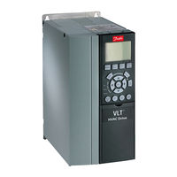
Danfoss VLT HVAC FC 100 Frequency Drive Manuals
Manuals and User Guides for Danfoss VLT HVAC FC 100 Frequency Drive. We have
4
Danfoss VLT HVAC FC 100 Frequency Drive manuals available for free PDF download: Service Manual, Instruction Manual, Operating Instructions Manual
Danfoss VLT HVAC FC 100 Service Manual (220 pages)
Brand:
Danfoss
| Category:
DC Drives
| Size: 18 MB
Table of Contents
Table of Contents
2
Introduction
12
Purpose
12
VLT FC Product Overview
12
For Your Safety
13
Electrostatic Discharge (ESD)
13
Frame Size Definitions
13
Tools Required
15
General Torque Tightening Values
15
Exploded Views
16
Ratings Tables
19
Operator Interface and Adjustable Frequency Drive Control
24
Introduction
24
User Interface
24
Numeric Local Control Panel (NLCP)
29
Tips and Tricks
30
Status Messages
30
Service Functions
36
Frequency Converter Inputs and Outputs
37
Input Signals
38
Output Signals
38
Control Terminals
39
Control Terminal Functions
40
Grounding Shielded Cables
42
Internal Adjustable Frequency Drive Operation
44
General
44
Description of Operation
44
Logic Section
45
Logic to Power Interface
46
Power Section
47
Sequence of Operation
48
Rectifier Section
48
Intermediate Section
50
Inverter Section
52
Brake Option
54
Cooling Fans
55
Fan Speed Control
55
Load Sharing
56
Specific Card Connections
57
Troubleshooting
58
Troubleshooting Tips
58
Exterior Fault Troubleshooting
58
Fault Symptom Troubleshooting
59
Visual Inspection
60
Fault Symptoms
61
No Display
61
Intermittent Display
61
Motor will Not Run
62
Incorrect Motor Operation
63
Warning/Alarm Messages
64
Warning/Alarm Code List
64
After Repair Tests
78
Adjustable Frequency Drive and Motor Applications
80
Torque Limit, Current Limit, and Unstable Motor Operation
80
Overvoltage Trips
81
Line Phase Loss Trips
82
Control Logic Problems
82
Programming Problems
83
Motor/Load Problems
84
Internal Adjustable Frequency Drive Problems
84
Overtemperature Faults
84
Current Sensor Faults
85
Signal and Power Wiring Considerations for Adjustable Frequency Drive Electromagnetic Compatibility
85
Effect of EMI
86
Sources of EMI
86
EMI Propagation
87
Preventive Measures
88
Proper EMC Installation
90
Test Procedures
92
Introduction
92
Tools Required for Testing
93
Signal Test Board
93
Test Cables
94
Static Test Procedures
95
Soft Charge and Rectifier Circuits Test: D-Frame Size
96
Soft Charge Rectifier Test: D-Frame Size
98
Soft Charge and Rectifier Circuits Test: E-Frame Size
100
Soft Charge Rectifier Test: E-Frame Size
102
Inverter Section Tests
103
Brake IGBT Test
104
Intermediate Section Tests
105
Heatsink Temperature Sensor Test
106
Fan Continuity Tests: D-Frame Size
106
Fan Continuity Tests: E-Frame Size
109
Dynamic Test Procedures
111
No Display Test
112
Input Voltage Test
112
Basic Control Card Voltage Test
113
Switch Mode Power Supply (SMPS) Test
114
Zero DC Bus Voltage Test
115
DC Undervoltage Test
115
Input Phase Imbalance Test
116
Input Waveform Test
117
Input SCR Test
118
Output Phase Imbalance Test
120
IGBT Gate Drive Signals Test
121
IGBT Switching Test
124
Brake IGBT Test
125
Current Sensors Test
125
Fan Tests
127
Input Terminal Signal Tests
129
Initial Start up or after Repair Drive Tests
130
Frame Sizes Disassembly and Assembly Instructions
132
Electrostatic Discharge (ESD)
132
Instructions
132
Control Card and Control Card Mounting Plate
132
Control Assembly Support Bracket
133
Power Card
134
Power Card Mounting Plate
135
Soft Charge Card
136
Gate Drive Card
137
Capacitor Bank(S)
138
Soft Charge (SC) Resistors D2/D4 Units
140
Soft Charge (SC) Resistors D1/D3 Units
141
Input Terminal Mounting Plate Assembly
144
Scr/Diode Module D2/D4 Units
145
Scr/Diode Module D1/D3 Units
149
Current Sensor
152
Heatsink Fan Assembly
153
AC Input Terminals
155
IGBT Modules D2/D4 Units
156
IGBT Modules D1/D3 Units
159
Frame Sizes Disassembly and Assembly Instructions
162
Electrostatic Discharge (ESD)
162
Instructions
162
Control Card and Control Card Mounting Plate
162
Power Card
164
Soft Charge Card
165
Gate Drive Card
166
Capacitor Banks
167
Input Terminal Mounting Plate Assy Option
169
Soft Charge Resistor
170
SCR and Diode Modules
171
Current Sensor
174
Heatsink Fan Assembly
175
AC Input, Motor, Load Sharing or Regen Terminals
176
IGBT Modules
177
Special Test Equipment
182
Test Equipment
182
Test Cables and SCR Shorting Plug Kit P/N 176F8439
182
Signal Test Board (P/N 176F8437)
183
Advertisement
Danfoss VLT HVAC FC 100 Instruction Manual (205 pages)
HVAC Low Harmonic Drive
Brand:
Danfoss
| Category:
DC Drives
| Size: 8 MB
Table of Contents
Table of Contents
2
How to Read this Instruction Manual
6
Copyright, Limitation of Liability and Revision Rights
6
Symbols
7
Safety
8
General Warning
9
Before Commencing Repair Work
9
Special Conditions
9
Avoid Unintended Start
10
Safe Stop Installation
10
Safe Stop of the Adjustable Frequency Drive
11
Line Power
13
Introduction to the Low Harmonic Drive
14
Working Principle
14
IEEE519 Compliance
15
Ordering Form Type Code
16
How to Install
18
How to Get Started
18
Pre-Installation
19
Planning the Installation Site
19
Receiving the Adjustable Frequency Drive
19
Transportation and Unpacking
19
Lifting
20
Mechanical Dimensions
20
Mechanical Installation
29
Assembly of F Frame Sections
31
Control Wire Connection between Drive and Filter
34
Terminal Locations - Frame Size D
35
Terminal Locations - Frame Size E
36
Terminal Locations - Frame Size F
38
Cooling and Airflow
40
Field Installation of Options
47
Installation of Input Plate Options
47
Installation of Line Power Shield for Adjustable Frequency Drives
47
Frame Size F Panel Options
48
Electrical Installation
50
Power Connections
50
AC Line Input Connections
63
Power and Control Wiring for Non-Shielded Cables
64
Fuses
65
Control Cable Routing
68
Electrical Installation, Control Terminals
70
Connection Examples for Control of Motor with External Signal Provider
71
Start/Stop
71
Pulse Start/Stop
72
Electrical Installation - Additional
74
Electrical Installation, Control Cables
74
Switches S201, S202, and S801
76
Final Set-Up and Test
77
Additional Connections
79
Mechanical Brake Control
79
Motor Thermal Protection
80
How to Operate the Low Harmonic Drive
82
How to Operate the Graphical LCP (GLCP)
82
How to Program the Low Harmonic Drive
94
How to Program the Adjustable Frequency Drive
94
Quick Menu Mode
96
Function Set-Ups
104
How to Program the Active Filter
135
Using the Low Harmonic Drive in NPN Mode
135
Parameter Lists - Adjustable Frequency Drive
136
Main Menu Structure
136
Operation and Display
137
Load / Motor
138
Brakes
139
Reference / Ramps
139
Limits / Warnings
140
Digital in / out
141
Analog in / out
142
Communication and Options
143
Profibus
144
CAN Fieldbus
144
Lonworks
145
Smart Logic Controller
145
Special Functions
146
FC Information
147
Data Readouts
148
Info & Readouts
149
FC Closed-Loop
149
Ext. Closed-Loop
150
Application Functions
151
Time-Based Funtions
152
Application Functions
153
Cascade Controller
154
Analog I / O Option MCB
155
Parameter Lists - Active Filter
156
Operation/Display 0
156
Digital In/Out 5
157
Comm. and Options 8
157
Special Functions 14
158
FC Information 15
159
Data Readouts 16
160
AF Settings 300
160
AF Readouts301
161
Installation and Set-Up
162
Network Configuration
165
FC Protocol Message Framing Structure
166
Examples
171
How to Access Parameters
172
General Specifications
174
Filter Specifications
181
Troubleshooting
182
Alarms and Warnings - Adjustable Frequency Drive (Right LCP)
182
Fault Messages
186
Alarms and Warnings - Filter (Left LCP)
193
Index
200
Danfoss VLT HVAC FC 100 Operating Instructions Manual (134 pages)
High Power
Brand:
Danfoss
| Category:
DC Drives
| Size: 11 MB
Table of Contents
Table of Contents
1
How to Read These Operating Instructions
5
Approvals
6
Symbols
6
Abbreviations
7
Safety Instructions and General Warning
9
Safety Regulations FC
9
Disposal Instruction
9
High Voltage
10
Safety Instructions
10
Avoid Unintended Start
11
Safe Stop
11
Safe Stop Installation
12
IT Mains
12
How to Install
13
How to Get Started
13
Pre-Installation - High Power
14
Planning the Installation Site
14
Receiving the Frequency Converter
14
Transportation and Unpacking
14
Lifting
15
Enclosures
16
Rated Power
16
Mechanical Dimensions
17
Mechanical Installation
17
Tools Needed
17
General Considerations
18
Installation in Enclosures - IP00 / Chassis Units
27
Installation on the Wall - IP21 (NEMA 1) and IP54 (NEMA 12) Units
27
Floor Mounting - Pedestal Installation IP21 (NEMA1) and IP54 (NEMA12)
28
Gland/Conduit Entry - IP21 (NEMA 1) and IP54 (NEMA12)
30
IP21 Drip Shield Installation (D1 and D2 Enclosure)
31
Field Installation of Options
31
Installation on Pedestal
41
Electrical Installation
44
Control Wires
44
Power Connections
45
Mains Connection
53
Fuses
54
Electrical Installation, Control Terminals
56
Connection Examples
58
Start/Stop
58
Pulse Start/Stop
58
Speed Up/Down
59
Potentiometer Reference
59
Electrical Installation - Continued
60
Electrical Installation, Control Cables
60
Switches S201, S202, and S801
62
Final Set-Up and Test
63
Additional Connections
65
Motor Thermal Protection
65
How to Programme
67
Graphical (GLCP) and Numerical (NLCP) Display
67
How to Programme on the Graphical LCP
67
How to Programme on the Numerical Local Control Panel
68
Quick Set-Up
69
Parameter Descriptions
76
Special Functions
77
FC Information
77
Data Readouts
77
Info & Readouts
77
FC Closed Loop
77
Application Functions
77
Time Based Funtions
77
Cascade Controller
77
Analog I/O Option MCB
77
General Specifications
111
Warnings and Alarms
119
Alarm- and Status Messages
119
Annexes
125
Index
131
Advertisement
Danfoss VLT HVAC FC 100 Operating Instructions Manual (73 pages)
d-frame
Brand:
Danfoss
| Category:
DC Drives
| Size: 3 MB
Table of Contents
Table of Contents
4
1 Introduction
7
Interior Views
7
Purpose of the Manual
8
Additional Resources
8
Product Overview
8
Internal Frequency Converter Controller Functions
8
Frame Sizes and Power Ratings
9
2 Installation
10
Planning the Installation Site
10
Frequency Converter and Motor Pre-Installation Checklist
10
Mechanical Installation
10
Cooling
10
Lifting
11
Wall Mounting - IP21 (NEMA 1) and IP54 (NEMA 12) Units
11
Electrical Installation
11
General Requirements
11
Earth (Ground) Requirements
14
Leakage Current (>3.5 Ma)
14
Earthing (Grounding) IP20 Enclosures
15
Earthing (Grounding) IP21/54 Enclosures
15
Motor Connection
15
Motor Cable
18
Motor Rotation Check
18
AC Mains Input Connection
18
Control Wiring Connection
18
Access
19
Using Screened Control Cables
19
Earthing (Grounding) of Screened Control Cables
19
Control Terminal Types
20
Wiring to Control Terminals
20
Control Terminal Functions
21
Serial Communication
21
3 Start up and Commissioning
22
Pre-Start
22
Applying Power to the Frequency Converter
23
Basic Operational Programming
23
Local-Control Test
24
System Start up
25
4 User Interface
26
Local Control Panel
26
LCP Layout
26
Setting LCP Display Values
27
Display Menu Keys
27
Navigation Keys
28
Operation Keys
28
Back up and Copying Parameter Settings
28
Uploading Data to the LCP
29
Downloading Data from the LCP
29
Restoring Default Settings
29
Recommended Initialisation
29
Manual Initialisation
29
5 Programming
30
Introduction
30
Programming Example
30
Control Terminal Programming Examples
32
International/North American Default Parameter Settings
32
Parameter Menu Structure
33
Main Menu Structure
34
Remote Programming with MCT 10 Set-Up Software
38
6 Application Examples
39
Introduction
39
7 Status Messages
44
Status Display
44
Status Message Definitions Table
44
8 Warnings and Alarms
47
System Monitoring
47
Warning and Alarm Types
47
Warnings
47
Alarm Trip
47
Alarm Trip-Lock
47
Warning and Alarm Displays
47
Warning and Alarm Definitions
49
Fault Messages
51
9 Basic Troubleshooting
58
MG16D102 - VLT Is a Registered Danfoss Trademark
58
Start up and Operation
58
10 Specifications
61
Power-Dependent Specifications
61
General Technical Data
62
Fuse Tables
67
Protection
67
Non UL Compliance
67
UL Compliance
68
Connection Tightening Torques
68
Index
69
Advertisement
Related Products
Danfoss VLT HVACDrive
Danfoss VLT HVAC Drive FC 100 Series
Danfoss VLT HVAC
Danfoss VLT HVAC Series
Danfoss VLT 8202 AQUA
Danfoss VLT 2830
Danfoss VLT 5003
Danfoss VLT 5004
Danfoss VLT B1-B4
Danfoss VLT 5032-5052
Danfoss Categories
Controller
DC Drives
Thermostat
Control Unit
Air Compressor
More Danfoss Manuals
Login
Sign In
OR
Sign in with Facebook
Sign in with Google
Upload manual
Upload from disk
Upload from URL