Sign In
Upload
Manuals
Brands
Daikin Manuals
Air Conditioner
RMXS-L Series
Daikin RMXS-L Series Manuals
Manuals and User Guides for Daikin RMXS-L Series. We have
2
Daikin RMXS-L Series manuals available for free PDF download: Service Manual
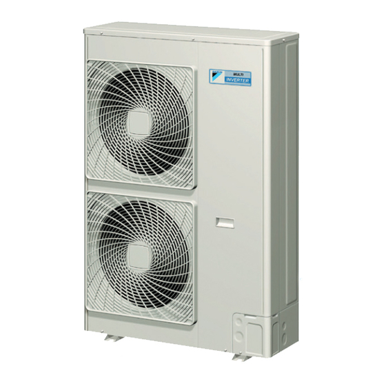
Daikin RMXS-L Series Service Manual (299 pages)
Multi-Split Type Air Conditioners
Brand:
Daikin
| Category:
Air Conditioner
| Size: 12.54 MB
Table of Contents
Table of Contents
3
Safety Considerations
8
Part 1 List of Functions
11
Functions
12
Indoor Unit
13
Part 2 Specifications
19
Specifications
20
Outdoor Unit
20
Branch Provider (BP) Unit
21
Indoor Unit
22
Ffq Series
30
Part 3 Printed Circuit Board Connector Wiring Diagram
31
1 Outdoor Unit
32
Rmxs48Lvju
32
2 Branch Provider (BP) Unit
35
Bpmks048A2U, Bpmks049A3U
35
3 Indoor Unit
36
Ctxg09/12/18Qvjuw(S)
36
Ctxs07Jvju, Ctxs09/12Hvju
38
Ctxs07Lvju, Ftxs09/12Lvju
40
Ftxs15/18/24Lvju
42
Fdxs09/12Lvju, Cdxs15/18/24Lvju
44
Fvxs09/12/15/18Nvju
46
Ffq09/12/15/18Q2Vju
48
4 Wired Remote Controller
49
Brc1E73
49
5 Wireless Remote Controller Kit
50
Brc082A41W, Brc082A42W(S)
50
Refrigerant Circuit Part 4
51
Part 4 Refrigerant Circuit
51
Refrigerant Circuit Part
52
1 Refrigerant Circuit
52
Outdoor Unit
52
Branch Provider (BP) Unit
53
2 Functional Parts Layout
54
3 Refrigerant Flow for each Operation Mode
56
Cooling Operation
56
Heating Operation
57
Cooling Oil Return Operation
58
Heating Oil Return Operation & Defrost Operation
59
Part 5 Functions and Control
60
1 Operation Mode
62
2 Basic Control
63
Normal Operation
63
Compressor PI Control
63
Electronic Expansion Valve PI Control
64
Cooling Operation Fan Control
65
3 Special Control
66
Startup Control
66
Oil Return Operation
67
Defrosting Operation
69
Pump-Down Residual Operation
69
Restart Standby
70
Stopping Operation
70
4 Protection Control
71
High Pressure Protection Control
71
Low Pressure Protection Control
72
Discharge Pipe Temperature Protection Control
73
Inverter Protection Control
74
Freeze-Up Protection Control
75
Dew Condensation Prevention Control
76
5 Other Control
77
Demand Control
77
Heating Operation Prohibition Control
77
6 Branch Provider (BP) Unit Control
78
Branch Provider (BP) Unit Command Conversion
78
Branch Provider (BP) Unit Electronic Expansion Valve Control
79
SH Control in Cooling Operation
81
SC Control in Heating Operation
82
Heat Exchanger Isothermal Control in Heating Operation
82
7 CTXG, CTXS, FTXS, CDXS, FDXS, FVXS Series Functions
83
Temperature Control
83
Airflow Direction Control
83
Fan Speed Control for Indoor Unit
87
Program Dry Operation
88
Automatic Operation
89
Thermostat Control
90
NIGHT SET Mode
91
ECONO Operation
92
HOME LEAVE Operation
92
2-Area INTELLIGENT EYE Operation
94
INTELLIGENT EYE Operation
96
POWERFUL Operation
97
Multi-Monitor Lamp/Timer Lamp
98
Clock Setting
99
WEEKLY TIMER Operation
100
Functions and Control
102
Other Functions
106
8 FFQ Series Function
108
Temperature Control
108
Airflow Direction Control
109
Fan Speed Control for Indoor Unit
109
Program Dry Operation
110
Clock and Calendar Setting (with Wired Remote Controller BRC1E73)
111
Schedule TIMER Operation (with Wired Remote Controller BRC1E73)
113
Setback Function (with Wired Remote Controller BRC1E73)
117
Drain Pump Control
117
Hot Start Control (in Heating Operation Only)
119
Presence and Floor Sensors (Option)
120
Other Functions
123
Part 6 Test Operation and Field Settings
124
1 Test Operation
125
Procedure and Outline
125
Operation When Power Is Turned on
127
Branch Provider (BP) Unit
128
CTXG, CTXS, FTXS, CDXS, FDXS, FVXS Series
130
FFQ Series
132
2 Field Settings
135
Outdoor Unit
135
Setting Mode 1 (H1P Off)
135
Setting Mode 2 (H1P On)
135
Demand
136
Capacity
137
Constant Demand Setting
137
Demand Setting
137
Night-Time Low Noise Setting
137
Off
138
Yes
138
Level
139
Capacity Precedence
139
Rated Power Consumption
145
Rated Power
146
CTXG, CTXS, FTXS, CDXS, FDXS, FVXS Series
149
Temperature Display Switch
150
When 2 Units Are Installed in 1 Room
151
Jumper and Switch Settings
153
FFQ Series
154
Part 7 Remote Controller
162
Applicable Remote Controller
163
Arc466A36
164
Arc452A9
166
Arc452A21
168
Arc452A23
170
Arc466A21
172
BRC1E73 (Wired Remote Controller)
174
Down Button
175
Operation Lamp
175
Fan Speed
178
Key Lock
178
Airflow Direction
179
BRC082A41W, BRC082A42W(S) (Wireless Remote Controller Kit)
180
Part 8 Troubleshooting
182
1 Troubleshooting with LED
184
Outdoor Unit
184
Branch Provider (BP) Unit
189
Indoor Unit
190
2 Service Diagnosis
192
CTXG, CTXS, FTXS, CDXS, FDXS, FVXS Series
192
FFQ Series
198
3 Error Codes and Description
204
4 Troubleshooting for CTXG, CTXS, FTXS, CDXS, FDXS, FVXS Series
206
Indoor Unit PCB Abnormality
206
Freeze-Up Protection Control/Heating Peak-Cut Control
208
Indoor Fan Motor or Related Abnormality
209
Thermistor or Related Abnormality
213
Front Panel Open/Close Fault
214
Check for CTXG, CTXS, FTXS, CDXS, FDXS, FVXS Series
215
Hall IC Check
216
5 Troubleshooting for FFQ Series
217
Indoor Unit PCB Abnormality
217
Drain Level Control System Abnormality
218
Indoor Fan Motor (DC Motor) or Related Abnormality
219
Humidifier or Related Abnormality
221
Thermistor or Related Abnormality
222
Presence Sensor or Floor Sensor Abnormality
223
Remote Controller Thermistor Abnormality
224
Signal Transmission Error (between Indoor Unit and Remote Controller)
225
Signal Transmission Error (between MAIN Remote Controller and SUB Remote Controller)
226
Mismatching of Indoor Unit and Outdoor Unit
227
Check for FFQ Series
228
6 Troubleshooting for Branch Provider (BP) Unit
229
Electronic Expansion Valve Abnormality
229
Branch Provider (BP) Unit PCB Abnormality
230
Branch Provider (BP) Liquid or Gas Pipe Thermistor Abnormality
231
Signal Transmission Error between Indoor Unit and Branch Provider (BP) Unit
232
Transmission Error between Outdoor Unit and Branch Provider (BP) Unit
234
Check for Branch Provider (BP) Unit
235
7 Troubleshooting for Outdoor Unit
236
Outdoor Unit PCB Abnormality
236
Troubleshooting
236
Actuation of High Pressure Switch
237
Actuation of Low Pressure Sensor
239
Compressor Motor Lock
241
Outdoor Fan Motor Abnormality
242
Moving Part of Electronic Expansion Valve (Y1E, Y3E) Abnormality
243
Discharge Pipe Temperature Abnormality
245
Refrigerant Overcharged
246
Outdoor Temperature Thermistor (R1T) Abnormality
247
Discharge Pipe Thermistor (R2T) Abnormality
248
Suction Pipe Thermistor (R3T, R5T) Abnormality
249
Outdoor Heat Exchanger Thermistor (R4T) Abnormality
250
Outdoor Liquid Pipe Thermistor (R7T) Abnormality
251
Subcooling Heat Exchanger Gas Pipe Thermistor (R6T) Abnormality
252
High Pressure Sensor Abnormality
253
Low Pressure Sensor Abnormality
254
Outdoor Unit PCB Abnormality
255
Radiation Fin Temperature Rise
256
Inverter Compressor Abnormality
257
Inverter Current Abnormality
258
Compressor Start-Up Error
259
High Voltage of Capacitor in Main Inverter Circuit
260
Radiation Fin Thermistor Abnormality
261
Low Pressure Drop Due to Refrigerant Shortage or Electronic Expansion Valve Abnormality
262
Power Supply Insufficient or Instantaneous Failure
264
Check Operation Is Not Conducted
265
Signal Transmission Error between Indoor Unit and Outdoor Unit in the same System
266
Excessive Number of Indoor Units
267
Address Duplication of Central Remote Controller
268
Transmission Error between Centralized Remote Controller and Indoor Unit
269
System Is Not Set yet
271
System Abnormality, Refrigerant System Address Undefined
272
Check for Outdoor Unit
273
8 Thermistor Resistance/Temperature Characteristics
277
9 Pressure Sensor
279
10 Method of Replacing Inverter's Power Transistors Modules
280
Part 9 Appendix
282
Piping Diagrams
283
Outdoor Unit
283
Branch Provider (BP) Unit
284
Indoor Unit
285
Wiring Diagrams
288
Outdoor Unit
288
Branch Provider (BP) Unit
289
Indoor Unit
290
Operation Limit
297
Advertisement
Daikin RMXS-L Series Service Manual (250 pages)
Multi-Split 8-Zone Heat Pump Systems
Brand:
Daikin
| Category:
Heat Pump
| Size: 9.87 MB
Table of Contents
Part 3 Printed Circuit Board Connector Wiring Diagram
23
Table of Contents
23
1 Outdoor Unit
24
Rmxs48Lvju
24
2 Branch Provider (BP) Unit
27
Bpmks048A2U, Bpmks049A3U
27
3 Indoor Unit
28
Ctxs07Lvju
28
Ctxs07Jvju, Ctxs09/12Hvju
30
Ftxs15/18/24Lvju
32
Fdxs09/12Lvju, Cdxs15/18/24Lvju
34
Ffq09/12/15/18Lvju
36
4 Wired Remote Controller
37
Brc1E72
37
5 Wireless Remote Controller
38
Brc7E830
38
Refrigerant Circuit Part 4
39
Refrigerant Circuit Part
40
1 Refrigerant Circuit
40
Outdoor Unit
40
Branch Provider (BP) Unit
41
2 Functional Parts Layout
42
3 Refrigerant Flow for each Operation Mode
44
Cooling Operation
44
Heating Operation
45
Cooling Oil Return Operation
46
Heating Oil Return Operation & Defrost Operation
47
Part 5 Function
48
1 Operation Mode
50
2 Basic Control
51
Normal Operation
51
Compressor PI Control
51
Electronic Expansion Valve PI Control
52
Cooling Operation Fan Control
53
3 Special Control
54
Startup Control
54
Oil Return Operation
55
Defrosting Operation
57
Pump-Down Residual Operation
57
Restart Standby
58
Stopping Operation
58
4 Protection Control
59
High Pressure Protection Control
59
Low Pressure Protection Control
60
Discharge Pipe Temperature Protection Control
61
Inverter Protection Control
62
Freeze-Up Protection Control
63
Dew Condensation Prevention Control
64
5 Other Control
65
Demand Control
65
Heating Operation Prohibition Control
65
6 Branch Provider (BP) Unit Control
66
Branch Provider (BP) Unit Command Conversion
66
Branch Provider (BP) Unit Electronic Expansion Valve Control
67
SH Control in Cooling Operation
69
SC Control in Heating Operation
70
Heat Exchanger Isothermal Control in Heating Operation
70
7 Function of CTXS, FTXS, CDXS, FDXS Series
71
Temperature Control
71
Airflow Direction Control (CTXS/FTXS Series Only)
72
Fan Speed Control for Indoor Unit
74
Program Dry Operation
75
Automatic Operation
76
Thermostat Control
77
NIGHT SET Mode
78
ECONO Operation
78
HOME LEAVE Operation
79
INTELLIGENT EYE Operation
81
Inverter POWERFUL Operation
82
Clock Setting
83
WEEKLY TIMER Operation
84
Other Functions
90
8 Function of FFQ Series
91
Drain Pump Control
91
Thermostat Sensor in Remote Controller
93
Freeze Prevention Control
95
Hot Start Control (in Heating Operation Only)
95
Part 6 Test Operation and Field Settings
96
1 Test Operation
97
Procedure and Outline
97
Operation When Power Is Turned on
99
Branch Provider (BP) Unit
100
RA Indoor Unit: CTXS, FTXS, CDXS, FDXS Series
102
SA Indoor Unit: FFQ Series
103
2 Field Settings
105
Outdoor Unit
105
Setting Mode 1 (H1P Off)
105
Setting Mode 2 (H1P On)
105
External Low Noise
107
Setting / Demand Setting
107
Night-Time Low Noise
107
Capacity Precedence Setting
107
Demand Setting
107
Constant Demand Setting
107
Off
110
H1P H2P H3P H4P H5P H6P H7P
110
Table of Contents
116
RA Indoor Unit: CTXS, FTXS, CDXS, FDXS Series
119
SA Indoor Unit: FFQ Series
122
Level
124
NO (Factory Setting)
124
Part 7 Remote Controller
130
Ctxs07Jvju, Ctxs09/12Hvju
131
Ctxs07Lvju, Ftxs15/18/24Lvju
133
Fdxs09/12Lvju, Cdxs15/18/24Lvju
135
Ffq09/12/15/18Lvju
137
BRC1E72> Wired Remote Controller
137
BRC7E830> Wireless Remote Controller
143
Part 8 Troubleshooting
145
1 Troubleshooting with LED
147
Outdoor Unit
147
Branch Provider (BP) Unit
152
Indoor Unit
153
2 Service Check Function
155
FFQ Series
157
3 Error Codes and Description
163
4 Troubleshooting for CTXS, FTXS, CDXS, FDXS Series
165
Indoor Unit PCB Abnormality
165
Freeze-Up Protection Control or Heating Peak-Cut Control
167
Fan Motor or Related Abnormality
169
Thermistor or Related Abnormality
173
Check for CTXS, FTXS, CDXS, FDXS Series
174
5 Troubleshooting for FFQ Series
176
Indoor Unit PCB Abnormality
176
Drain Level Control System Abnormality
177
Fan Motor or Related Abnormality
178
Drain System Abnormality
179
Thermistor or Related Abnormality
180
Remote Controller Thermistor Abnormality
181
Signal Transmission Error between Remote Controller and Indoor Unit
182
Signal Transmission Error between MAIN Remote Controller and SUB Remote Controller
183
Field Setting Abnormality
184
6 Troubleshooting for Branch Provider (BP) Unit
185
Electronic Expansion Valve Abnormality
185
Branch Provider (BP) Unit PCB Abnormality
186
Branch Provider (BP) Liquid or Gas Pipe Thermistor Abnormality
187
Signal Transmission Error between Indoor Unit and Branch Provider (BP) Unit
188
Transmission Error between Outdoor Unit and Branch Provider (BP) Unit
190
Check for Branch Provider (BP) Unit
191
7 Troubleshooting for Outdoor Unit
192
Outdoor Unit PCB Abnormality
192
Actuation of High Pressure Switch
193
Actuation of Low Pressure Sensor
195
Compressor Motor Lock
197
Outdoor Fan Motor Abnormality
198
Moving Part of Electronic Expansion Valve (Y1E, Y3E) Abnormality
199
Discharge Pipe Temperature Abnormality
201
Refrigerant Overcharged
202
Outdoor Temperature Thermistor (R1T) Abnormality
203
Discharge Pipe Thermistor (R2T) Abnormality
204
Suction Pipe Thermistor (R3T, R5T) Abnormality
205
Outdoor Heat Exchanger Thermistor (R4T) Abnormality
206
Outdoor Liquid Pipe Thermistor (R7T) Abnormality
207
Subcooling Heat Exchanger Gas Pipe Thermistor (R6T) Abnormality
208
High Pressure Sensor Abnormality
209
Low Pressure Sensor Abnormality
210
Outdoor Unit PCB Abnormality
211
Radiation Fin Temperature Rise
212
Inverter Compressor Abnormality
213
Inverter Current Abnormality
214
Compressor Start-Up Error
215
High Voltage of Capacitor in Main Inverter Circuit
216
Radiation Fin Thermistor Abnormality
217
Low Pressure Drop Due to Refrigerant Shortage or Electronic Expansion Valve Abnormality
218
Power Supply Insufficient or Instantaneous Failure
220
Check Operation Is Not Conducted
221
Signal Transmission Error between Indoor Unit and Outdoor Unit in the same System
222
Excessive Number of Indoor Units
223
Address Duplication of Central Remote Controller
224
Transmission Error between Centralized Remote Controller and Indoor Unit
225
System Is Not Set yet
227
System Abnormality, Refrigerant System Address Undefined
228
Check for Outdoor Unit
229
8 Thermistor Resistance / Temperature Characteristics
233
9 Pressure Sensor
235
10 Method of Replacing Inverter's Power Transistors Modules
236
Piping Diagrams
239
Outdoor Unit
239
Branch Provider (BP) Unit
240
Indoor Unit
241
Wiring Diagrams
243
Outdoor Unit
243
Branch Provider (BP) Unit
244
Indoor Unit
245
Removal Procedure (Booklet No.)
248
Advertisement
Related Products
Daikin RMXS48LVJU
Daikin RMXS112E7V3B
Daikin RMXS140E7V3B
Daikin RMXS160E7V3B
Daikin RMXS160D7V3B
Daikin RMXS112DV1A
Daikin RMXS140DV1A
Daikin RMXS112DVLT
Daikin RMXS140DVLT
Daikin RMXS112DVM
Daikin Categories
Air Conditioner
Heat Pump
Remote Control
Chiller
Fan
More Daikin Manuals
Login
Sign In
OR
Sign in with Facebook
Sign in with Google
Upload manual
Upload from disk
Upload from URL