Sign In
Upload
Manuals
Brands
Daikin Manuals
Heat Pump
FDMQ-R Series
Daikin FDMQ-R Series Ducted Heat Pump Manuals
Manuals and User Guides for Daikin FDMQ-R Series Ducted Heat Pump. We have
5
Daikin FDMQ-R Series Ducted Heat Pump manuals available for free PDF download: Manual, Service Manual
Daikin FDMQ-R Series Manual (484 pages)
Brand:
Daikin
| Category:
Heat Pump
| Size: 56 MB
Table of Contents
Split Type Air Conditioners
3
Table of Contents
3
1 Lineup
6
2 Functions
7
3 Specifications
9
4 Dimensions
16
Indoor Unit
16
Outdoor Unit
21
5 Wiring Diagrams
23
Indoor Unit
23
Outdoor Unit
26
6 Piping Diagrams
28
Indoor Unit
28
Outdoor Unit
30
7 Capacity Tables
33
Capacity Correction Factor by the Length of Refrigerant Piping (Reference)
55
8 Operation Limit
57
9 Fan Characteristics
58
External Static Pressure
58
Airflow Auto Adjustment
61
Indoor Unit
64
Outdoor Unit
69
Ftx18/24Uvju
72
Section 2
73
Indoor Unit Installation Diagram
76
Indoor Unit
76
Wireless Remote Controller
76
Indoor Unit Installation
77
Installing the Mounting Plate
77
Drilling a Wall Hole and Installing Wall Embedded Pipe
78
Installing the Indoor Unit
78
Wiring
80
Drain Piping
80
Refrigerant Piping Work
81
Flaring the Pipe End
81
Refrigerant Piping
81
Installation Tips
82
Removing and Installing the Front Panel
82
Removing and Installing the Front Grille
83
How to Set the Different Addresses
83
Trial Operation and Testing
84
Test Items
84
Section 3
85
Choosing an Installation Site
87
Indoor Unit
87
Wireless Remote Controller
87
Accessories
87
Indoor Unit Installation Diagram
88
Indoor Unit Installation
89
Installing the Mounting Plate
89
Drilling a Wall Hole and Installing Wall Embedded Pipe
89
Installing the Indoor Unit
89
Wiring
90
Drain Piping
91
Refrigerant Piping Work
92
Flaring the Pipe End
92
Refrigerant Piping
92
Installation Tips
93
Removing and Installing the Front Panel
93
Removing and Installing the Front Grille
93
How to Set the Different Addresses
93
When Connecting to an HA System
93
Trial Operation and Testing
94
Test Items
94
Section 4
95
Accessories
97
Choosing an Installation Site
97
Indoor Unit
97
Wireless Remote Controller
97
Indoor Unit Installation Diagram
98
Indoor Unit Installation
99
Refrigerant Piping
99
Drilling a Wall Hole and Installing Wall Embedded Pipe
101
Drain Piping
101
Installing Indoor Unit
102
Preparation
102
Installation
103
Flaring the Pipe End
106
Connecting the Refrigerant Pipe
106
Caution on Piping Handling
107
Selection of Copper and Heat Insulation Materials
107
Checking for Gas Leakage
107
Attaching the Connection Pipe
107
Wiring
108
When Connecting to an HA System
109
How to Set the Different Addresses
110
Section 5
156
Trial Operation and Testing
167
Test Items
167
Safety Considerations
168
Accessories
170
Precautions for Selecting a Location
170
Outdoor Unit Installation Diagram
171
Precautions on Installation
171
Installation Space Requirements
172
Installing the Outdoor Unit
172
Outdoor Unit Installation
172
Drain Work
173
Flaring the Pipe End
173
Models, Excluding RXL Models)
173
Refrigerant Piping
173
Pressure Test and Evacuating System
174
Refilling Refrigerant
175
Wiring
176
Facility Setting (Cooling at Low Outdoor Temperature)
178
Pump down Operation
178
Test Items
191
Trial Operation and Testing
191
Section 6
402
Features and Functions
403
Names and Functions of the Operating Section
404
Operation
405
Individual Screen, All Screen, Zone Screen
405
Batch Operation and Stop Method
406
Group Operation and Stop Method
406
Registering Zones
406
Zone Operation and Stop Method
407
Changing the Fan Direction and Fan Strength
408
Changing the Ventilation Mode and Ventilation Strength
408
Timer Number Setting
408
Setting the Operation Code
409
Operation Mode
410
Setting Operation Mode
413
Group Monitoring
413
Error Diagnosing Function
414
Setting Master Remote Controller
417
Display of Time to Clean
418
Installation Table
419
Optional Accessories
420
Double Central Remote Controllers
420
Specifications
421
Outline Drawings
421
Names and Functions of Operating Section
442
Operation
443
Setting Present Time
443
Setting No. of Programmed Time
444
Change and Cancellation of No. of Programmed Time
445
Manual Operation
447
Operation Control Code
447
Error Diagnosing Function
447
Question and Answer
448
Advertisement
Daikin FDMQ-R Series Service Manual (242 pages)
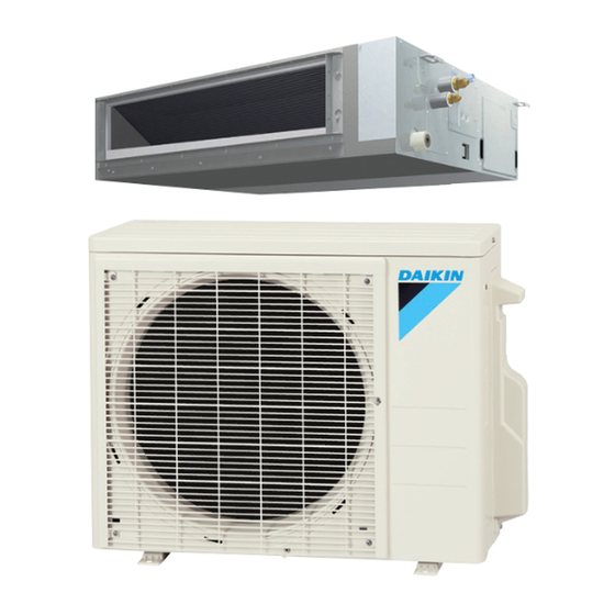
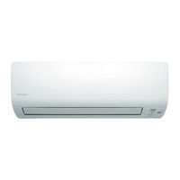
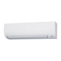
Inverter Pair: Wall Mounted Type, Floor Standing Type, Duct Connected Type.
Brand:
Daikin
| Category:
Air Conditioner
| Size: 23 MB
Table of Contents
Table of Contents
2
Introduction
6
Safety Cautions
7
Warnings and Cautions Regarding Safety of Workers
7
Warnings and Cautions Regarding Safety of Users
9
Icons Used
12
Revision History
13
Part 1 General Information
14
Applicable Models
15
Functions
16
Part 2 Specifications
18
Specifications
19
Part 3 Printed Circuit Board Connector Wiring Diagram
26
Indoor Unit
27
Ftx09/12Nmvju
27
Ftx15Nmvju
29
Ftx18/24Uvju
31
Fvxs09/12/15Nvju
33
Fdmq12/18/24Rvju
35
Wireless Remote Controller Receiver
37
Brc082A43
37
Wired Remote Controller
38
Brc1E73
38
Outdoor Unit
39
Rxl09Qmvju
39
Rxl12Qmvju(9)
41
Rxl15Qmvju
43
Rxl18/24Umvju
44
Optional Adaptor
47
BRP072A43 Wireless LAN Adaptor
47
KRP067A41/KRP980B2 Remote Control PC-Board Set
47
Part 4 Functions and Control
48
Common Functions
49
Temperature Control
49
Frequency Principle
49
Functions for FTX, FVXS Series
51
Airflow Direction Control
51
COMFORT AIRFLOW Operation
54
Fan Speed Control for Indoor Unit
55
Program Dry Operation
56
Automatic Cooling/Heating Changeover
57
Thermostat Control
58
NIGHT SET Mode
59
ECONO Operation
60
INTELLIGENT EYE Operation
61
POWERFUL Operation
62
Clock Setting
63
WEEKLY TIMER Operation
64
Other Functions
70
Functions for FDMQ Series
71
Fan Speed Control for Indoor Unit
71
Program Dry Operation
72
Clock and Calender Setting (with BRC1E73)
73
Schedule Timer Operation (with BRC1E73)
75
Drain Pump Control
78
Hot Start Control (in Heating Operation Only)
80
Other Functions
81
Thermistor Functions
82
Control Specification
83
Mode Hierarchy
83
Frequency Control
83
Controls at Mode Changing/Start-Up
85
Discharge Pipe Temperature Control
87
Input Current Control
88
Freeze-Up Protection Control
89
Heating Peak-Cut Control
89
Outdoor Fan Control
90
Liquid Compression Protection Function
90
Defrost Control
91
Electronic Expansion Valve Control
92
Malfunctions
95
Part 5 Remote Controller
96
Applicable Remote Controller
97
Arc466A21
98
Arc466A37
100
Arc480A8
102
Brc082A43
103
Brc1E73
105
Part 6 Service Diagnosis
111
General Problem Symptoms and Check Items
113
Troubleshooting with LED
114
Indoor Unit
114
Outdoor Unit
115
Service Diagnosis
116
ARC480 Series
116
ARC466 Series
119
Brc1E73
122
Brc082A43
124
Error Codes and Description
128
Troubleshooting for FTX, FVXS Series
129
Indoor Unit PCB Abnormality
129
Freeze-Up Protection Control/Heating Peak-Cut Control
131
Indoor Fan Motor (DC Motor) or Related Abnormality
133
Thermistor or Related Abnormality
137
Low-Voltage Detection or Over-Voltage Detection
138
Signal Transmission Error (between Indoor Unit and Outdoor Unit)
140
Unspecified Voltage (between Indoor Unit and Outdoor Unit)
142
Troubleshooting for FDMQ Series
143
Indoor Unit PCB Abnormality
143
Drain Level Control System Abnormality
144
Indoor Fan Motor (DC Motor) or Related Abnormality
145
Indoor Fan PCB Abnormality
147
Humidifier or Related Abnormality
148
Thermistor or Related Abnormality
149
Remote Controller Thermistor Abnormality
150
Low-Voltage Detection or Over-Voltage Detection
151
Signal Transmission Error (between Indoor and Outdoor Unit)
153
Signal Transmission Error (between Indoor Unit and Remote Controller)
155
Signal Transmission Error (between MAIN/SUB Remote Controllers)
156
Mismatching of Indoor Unit and Outdoor Unit
157
Troubleshooting for Outdoor Unit
158
Outdoor Unit PCB Abnormality
158
OL Activation (Compressor Overload)
159
Compressor Lock
162
DC Fan Lock
163
Input Overcurrent Detection
164
Four Way Valve Abnormality
166
Discharge Pipe Temperature Control
168
High Pressure Control in Cooling
170
System Shutdown Due to Temperature Abnormality in the Compressor
172
Compressor Sensor System Abnormality
173
Position Sensor Abnormality
174
Thermistor or Related Abnormality (Outdoor Unit)
177
Electrical Box Temperature Rise
179
Radiation Fin Temperature Rise
181
Output Overcurrent Detection
183
Signal Transmission Error on Outdoor Unit PCB
185
Check
186
Thermistor Resistance Check
186
Indoor Fan Motor Connector Check
187
Power Supply Waveform Check
189
Electronic Expansion Valve Check
189
Four Way Valve Performance Check
190
Inverter Unit Refrigerant System Check
190
Inverter Analyzer Check
191
Rotation Pulse Check on the Outdoor Unit PCB
194
Installation Condition Check
195
Discharge Pressure Check
195
Outdoor Fan System Check
196
Main Circuit Short Check
196
Power Module Check
199
Part 7 Trial Operation and Field Settings
202
Pump down Operation
203
Forced Cooling Operation
204
Trial Operation
207
Field Settings for FTX, FVXS Series
211
Temperature Display Switch
211
When 2 Units Are Installed in 1 Room
212
Jumper and Switch Settings
214
Field Settings for FDMQ Series
215
How to Change the Field Settings
215
Overview of Field Settings
218
MAIN/SUB and Address Setting for Wireless Remote Controller
219
Field Settings for Outdoor Unit
222
Facility Setting (Cooling at Low Outdoor Temperature)
222
Drain Pan Heater
223
Silicone Grease on Power Transistor/Diode Bridge
224
Part 8 Appendix
225
Piping Diagrams
226
Indoor Unit
226
Outdoor Unit
228
Wiring Diagrams
231
Indoor Unit
231
Outdoor Unit
236
Operation Limit
241
Daikin FDMQ-R Series Manual (152 pages)
Inverter Pair Duct Connected Type
Brand:
Daikin
| Category:
Inverter
| Size: 4 MB
Table of Contents
Table of Contents
3
Safety Cautions
6
Warnings and Cautions Regarding Safety of Workers
6
Warnings and Cautions Regarding Safety of Users
8
Icons Used
11
Part 1 List of Functions
12
Functions
13
Part 2 Specifications
14
Specifications
15
Part 3 Printed Circuit Board Connector Wiring Diagram
20
Indoor Unit
21
Fdmq09/12/15/18/24Rvju
21
Wired Remote Controller
23
Brc1E73
23
Wireless Remote Controller Receiver
24
Brc082A43
24
Outdoor Unit
25
Rx09/12R
25
Rx15/18/24R
26
Part 4 Functions and Control
27
Main Functions
28
Temperature Control
28
Frequency Principle
28
Fan Speed Control for Indoor Unit
30
Program Dry Operation
31
Clock and Calendar Setting (with Wired Remote Controller BRC1E73)
32
Schedule TIMER Operation (with Wired Remote Controller BRC1E73)
34
Drain Pump Control
37
Hot Start Control (in Heating Operation Only)
39
Other Functions
40
Control Specification
41
Mode Hierarchy
41
Frequency Control
42
Controls at Mode Changing/Start-Up
44
Discharge Pipe Temperature Control
46
Input Current Control
47
Freeze-Up Protection Control
48
Heating Peak-Cut Control
49
Outdoor Fan Control
50
Liquid Compression Protection Function
50
Defrost Control
51
Electronic Expansion Valve Control
52
Malfunctions
55
Part 5 Remote Controller
56
Wired Remote Controller (BRC1E73)
57
Wireless Remote Controller (BRC082A43)
63
Part 6 Service Diagnosis
65
General Problem Symptoms and Check Items
67
Troubleshooting with LED
68
Indoor Unit
68
Outdoor Unit
68
Service Diagnosis
69
Wired Remote Controller (BRC1E73)
69
Wireless Remote Controller (BRC082A43)
71
Troubleshooting
75
Error Codes and Description
75
Indoor Unit PCB Abnormality
76
Drain Level Control System Abnormality
77
Indoor Fan Motor (DC Motor) or Related Abnormality
78
Indoor Fan PCB Abnormality
80
Humidifier or Related Abnormality
81
Thermistor or Related Abnormality
82
Remote Controller Thermistor Abnormality
83
Signal Transmission Error (between Indoor Unit and Remote Controller)
84
Signal Transmission Error (between MAIN Remote Controller and SUB Remote Controller)
85
Low-Voltage Detection or Over-Voltage Detection
86
Signal Transmission Error (between Indoor Unit and Outdoor Unit)
88
Mismatching of Indoor Unit and Outdoor Unit
90
Outdoor Unit PCB Abnormality
91
OL Activation (Compressor Overload)
92
OL Activation (Compressor Overload) or HPS Activation (High Pressure Switch)
94
Compressor Lock
97
DC Fan Lock (Outdoor Fan Motor)
98
Input Overcurrent Detection
99
Four Way Valve Abnormality
100
Discharge Pipe Temperature Control
102
High Pressure Control in Cooling
103
System Shutdown Due to Temperature Abnormality in Compressor
105
Compressor System Sensor Abnormality
106
Position Sensor Abnormality
107
DC Voltage/Current Sensor Abnormality
109
Thermistor or Related Abnormality (Outdoor Unit)
110
Electrical Box Temperature Rise
112
Radiation Fin Temperature Rise
113
Output Overcurrent Detection
114
Check
116
Thermistor Resistance Check
116
Indoor Fan Motor Connector Check
117
Power Supply Waveforms Check
117
Electronic Expansion Valve Check
118
Four Way Valve Performance Check
119
Inverter Unit Refrigerant System Check
119
Inverter Analyzer Check
120
Outdoor Fan Motor Check
122
Installation Condition Check
123
Discharge Pressure Check
123
Outdoor Fan System Check
124
Main Circuit Short Check
124
Power Module Check
126
Part 7 Trial Operation and Field Settings
128
Pump down Operation
129
Forced Cooling Operation
130
Trial Operation
131
Field Settings
134
How to Change the Field Settings
134
Overview of the Field Settings
137
MAIN/SUB and Address Setting for Wireless Remote Controller
138
Facility Setting (Cooling at Low Outdoor Temperature)
140
Silicone Grease on Power Transistor/Diode Bridge
141
Part 8 Appendix
142
Piping Diagrams
143
Indoor Unit
143
Outdoor Unit
144
Wiring Diagrams
146
Indoor Unit
146
Outdoor Unit
147
Operation Limit
150
Advertisement
Daikin FDMQ-R Series Service Manual (146 pages)
Inverter Pair Duct Connected Type
Brand:
Daikin
| Category:
Inverter
| Size: 3 MB
Table of Contents
Table of Contents
3
Safety Cautions
6
Warnings and Cautions Regarding Safety of Workers
6
Warnings and Cautions Regarding Safety of Users
8
Icons Used
11
Part 1 List of Functions
12
Functions
13
Part 2 Specifications
14
Specifications
15
Part 3 Printed Circuit Board Connector Wiring Diagram
19
Indoor Unit
20
Fdmq09/12/15/18/24Rvju
20
Wired Remote Controller
22
Brc1E73
22
Wireless Remote Controller Receiver
23
Brc082A43
23
Outdoor Unit
24
Rx09/12Rmvju(9)
24
Rx15/24Rmvju(A), Rx18Rmvju(9)(A)
25
Part 4 Functions and Control
26
Main Functions
27
Temperature Control
27
Frequency Principle
27
Fan Speed Control for Indoor Unit
29
Program Dry Operation
30
Clock and Calendar Setting (with Wired Remote Controller BRC1E73)
31
Schedule TIMER Operation (with Wired Remote Controller BRC1E73)
33
Drain Pump Control
36
Hot Start Control (in Heating Operation Only)
38
Other Functions
39
Control Specification
40
Mode Hierarchy
40
Frequency Control
41
Controls at Mode Changing/Start-Up
43
Discharge Pipe Temperature Control
45
Input Current Control
46
Freeze-Up Protection Control
47
Heating Peak-Cut Control
48
Outdoor Fan Control
49
Liquid Compression Protection Function
49
Defrost Control
50
Electronic Expansion Valve Control
51
Malfunctions
54
Part 5 Remote Controller
55
Wired Remote Controller (BRC1E73)
56
Wireless Remote Controller (BRC082A43)
62
Part 6 Service Diagnosis
64
General Problem Symptoms and Check Items
66
Troubleshooting with LED
67
Indoor Unit
67
Outdoor Unit
67
Service Diagnosis
68
Wired Remote Controller (BRC1E73)
68
Wireless Remote Controller (BRC082A43)
70
Troubleshooting
74
Error Codes and Description
74
Indoor Unit PCB Abnormality
75
Drain Level Control System Abnormality
76
Indoor Fan Motor (DC Motor) or Related Abnormality
77
Indoor Fan PCB Abnormality
79
Humidifier or Related Abnormality
80
Thermistor or Related Abnormality
81
Remote Controller Thermistor Abnormality
82
Signal Transmission Error (between Indoor Unit and Remote Controller)
83
Signal Transmission Error (between MAIN Remote Controller and SUB Remote Controller)
84
Signal Transmission Error
84
(Between MAIN Remote Controller and SUB Remote Controller)
84
Low-Voltage Detection or Over-Voltage Detection
85
Signal Transmission Error (between Indoor Unit and Outdoor Unit)
87
Mismatching of Indoor Unit and Outdoor Unit
89
Outdoor Unit PCB Abnormality
90
OL Activation (Compressor Overload)
91
Compressor Lock
93
DC Fan Lock (Outdoor Fan Motor)
94
Input Overcurrent Detection
95
Four Way Valve Abnormality
96
Discharge Pipe Temperature Control
98
High Pressure Control in Cooling
99
System Shutdown Due to Compressor Internal Temperature Abnormality
101
Compressor System Sensor Abnormality
102
Position Sensor Abnormality
103
Thermistor or Related Abnormality (Outdoor Unit)
105
Electrical Box Temperature Rise
107
Radiation Fin Temperature Rise
108
Output Overcurrent Detection
109
Check
111
Thermistor Resistance Check
111
Indoor Fan Motor Connector Check
112
Power Supply Waveforms Check
112
Electronic Expansion Valve Check
113
Four Way Valve Performance Check
114
Inverter Unit Refrigerant System Check
114
Inverter Analyzer Check
115
Rotation Pulse Check on the Outdoor Unit PCB
117
Installation Condition Check
118
Discharge Pressure Check
118
Outdoor Fan System Check
119
Main Circuit Short Check
119
Power Module Check
121
Part 7 Trial Operation and Field Settings
123
Pump down Operation
124
Forced Cooling Operation
125
Trial Operation
126
Field Settings
129
How to Change the Field Settings
129
Overview of the Field Settings
132
MAIN/SUB and Address Setting for Wireless Remote Controller
133
Facility Setting (Cooling at Low Outdoor Temperature)
135
Silicone Grease on Power Transistor/Diode Bridge
136
Part 8 Appendix
137
Piping Diagrams
138
Indoor Unit
138
Outdoor Unit
139
Wiring Diagrams
141
Indoor Unit
141
Outdoor Unit
142
Operation Limit
144
Daikin FDMQ-R Series Service Manual (20 pages)
Inverter Pair Duct Connected Type
Brand:
Daikin
| Category:
Heat Pump
| Size: 1 MB
Advertisement
Related Products
Daikin FDYM60FAV1
Daikin FDYM03FAV1
Daikin Super Multi NX FDXS12LVJ
Daikin FDXS-L Series
Daikin FDXV41NVLT
Daikin FDXV50NVLT
Daikin FDXV63NVLT
Daikin FDXV71NVLT
Daikin FDXS25EV2C
Daikin FDXS35EV2C
Daikin Categories
Air Conditioner
Heat Pump
Chiller
Remote Control
Air Handlers
More Daikin Manuals
Login
Sign In
OR
Sign in with Facebook
Sign in with Google
Upload manual
Upload from disk
Upload from URL