Sign In
Upload
Manuals
Brands
Bitzer Manuals
Air Compressor
KT-230-2
Bitzer KT-230-2 Manuals
Manuals and User Guides for Bitzer KT-230-2. We have
1
Bitzer KT-230-2 manual available for free PDF download: Technical Information
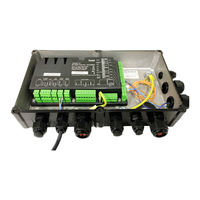
Bitzer KT-230-2 Technical Information (86 pages)
Compressor module for reciprocating compressors
Brand:
Bitzer
| Category:
Air Compressor
| Size: 5.89 MB
Table of Contents
English
2
Table of Contents
2
1 Introduction
4
2 Safety
4
Also Observe the Following Technical Documents
4
Authorized Staff
5
Residual Risks
5
Safety References
5
General Safety References
5
3 Technical Data
6
4 Peripheral Devices
8
Standard
8
Options
8
Peripheral Devices for Compressors for Standard Refrigerants
9
Peripheral Devices for Compressors for Transcritical CO 2 Applications
9
Dimensional Drawings
10
Dimensional Drawings for Compressors for Transcritical CO Applications with CM-RC-01
11
The Refrigerant Injection System
11
Minimum Equipment for the RI System
12
Integrating the RI System into the Refrigeration Circuit
12
5 Operating and Monitoring Functions
12
Operating Functions
12
CRII Capacity Control
12
SU Start Unloading
13
Compressor Cooling
13
Oil Heater
13
Switching Times of the Motor Contactors at Compressor Start
13
Monitoring and Protective Functions
13
6 Mounting the Peripheral Devices Enclosed in the Delivery
14
Assemble Components for Application Limit Monitoring
14
Install Additional Fan (M2)
14
Installing the RI System
14
7 Electrical Connection
15
Representation of Components and Cables
15
Schematic Wiring Diagram for Direct On-Line Start
15
Schematic Wiring Diagram for Part Winding Start
15
Schematic Wiring Diagram for Star-Delta Start
15
Principle Circuit Diagram for Operation with Frequency Inverter (FI)
15
Legend for the Schematic Wiring Diagrams
16
Wiring in the State of Delivery
21
Compressors for Standard Refrigerants
21
Compressors for Transcritical CO Applications
21
High Pressure Switch
21
8 Connecting Cables
21
Compressor Power Connection
21
Required Electrical Connections on the CM-RC-01
22
Module Power Connection to Terminal Strip CN1
22
Input Signal of the Safety Chain
22
Motor Contactors
22
Command for Compressor Start-Up
22
Control Signal from Superior Controller
23
Connecting High-Pressure Switches Electrically
23
Close Module Housing
23
Electrical Connection of the Enclosed Peripheral Devices
23
Connect the Additional Fan (M2) Electrically to the CM-RC-01
23
Controlling the CRII Capacity Controller with the System Controller
24
Control Via Analogue Signal
24
Control Via Modbus Interface
25
Connecting Operation Monitoring Via the BEST SOFTWARE
25
Close Module Housing
25
9 Protective Functions
25
Reset
26
Automatic Time-Delayed Reset
26
External Reset
27
Alarm List
27
10 Monitoring the Operating Parameters Using the BEST SOFTWARE
27
Establishing Communication Via the BEST SOFTWARE
27
Configuring the CM-RC-01 with the BEST SOFTWARE
28
Setting the Current Time
28
Selecting the Motor Start Function
28
Activating Peripheral Devices
28
Activating Application Limits Monitoring
28
Activating High- and Low-Pressure Switches
29
Configuring a Spare Part
29
Data Log
29
Deutsch
30
2 Sicherheit
32
Zusätzlich Folgende Technische Dokumente Beachten
32
Autorisiertes Fachpersonal
32
Restgefahren
33
Sicherheitshinweise
33
Allgemeine Sicherheitshinweise
33
3 Technische Daten
34
4 Peripheriegeräte
36
Standard
36
Optionen
36
Peripheriegeräte von Verdichtern für Standardkältemittel
36
Anwendungen
36
Maßzeichnungen
38
Maßzeichnungen von Verdichtern für Transkritische CO
39
Das RI-System
39
Minimalausstattung für das RI-System
40
RI-System in den Kältekreislauf Einbinden
40
5 Betriebs- und Überwachungsfunktionen
40
Betriebsfunktionen
40
Leistungsregelung CRII
40
Anlaufentlastung SU
40
Verdichterkühlung
40
Ölheizung
41
Schaltzeiten der Motorschütze Beim Verdichteranlauf
41
Überwachungs- und Schutzfunktionen
41
6 Beigepackte Peripheriegeräte Montieren
42
Bauteile für die Einsatzgrenzüberwachung Montieren
42
Zusatzventilator (M2) Montieren
42
RI-System Montieren
42
7 Elektrischer Anschluss
43
Darstellung von Bauteilen und Kabeln
43
Prinzipschaltbild für Direktanlauf
43
Prinzipschaltbild für Teilwicklungsanlauf
43
Prinzipschaltbild für Stern-Dreieck-Anlauf
43
Prinzipschaltbild für Betrieb mit Frequenzumrichter (FU)
44
Legende zu den Prinzipschaltbildern
44
Verkabelung IM Auslieferungszustand
49
Verdichter für Standardkältemittel
49
Verdichter für Transkritische CO Anwendungen
49
Hochdruckschalter
49
8 Kabel Anschließen
49
Verdichterleistungsanschluss
49
Modulleistungsanschluss an Klemmleiste CN1
50
Eingangsignal der Sicherheitskette
50
Motorschütze
50
Befehl für Verdichteranlauf
50
Regelsignal vom Übergeordneten Regler
51
Hochdruckschalter Elektrisch Anschließen
51
Modulgehäuse Schließen
51
Elektrischer Anschluss der Beigepackten Peripheriegeräte
51
Einsatzgrenzüberwachung Elektrisch an das CM-RC-01 Anschließen
51
Leistungsregelung CRII mit dem Anlagenregler Steuern
52
Steuerung über Analogsignal
52
Steuerung über Modbus-Schnittstelle
53
Betriebsüberwachung mit der BEST SOFTWARE Anschließen
53
Modulgehäuse Schließen
53
9 Schutzfunktionen
53
Entriegeln
54
Automatische Zeitverzögerte Entriegelung
54
Extern Entriegeln
55
Alarmliste
55
10 Betriebsparameter mit der BEST SOFTWARE Überwachen
55
Kommunikation über die BEST SOFTWARE Aufbauen
55
CM-RC-01 mit der BEST SOFTWARE Konfigurieren
56
Aktuelle Uhrzeit Einstellen
56
Motoranlauffunktion Auswählen
56
Peripheriegeräte Aktivieren
56
Einsatzgrenzüberwachung Aktivieren
56
Hoch- und Niederdruckschalter Aktivieren
57
Ersatzteil Konfigurieren
57
Datenaufzeichnung
57
Français
58
1 Préface
60
2 Sécurité
60
Tenir Compte en Outre des Documents Techniques Suivants
60
Personnel Spécialisé Autorisé
60
Dangers Résiduels
61
Indications de Sécurité
61
Indications de Sécurité Générales
61
3 Caractéristiques Techniques
62
4 Dispositifs Périphériques
64
Standard
64
Options
64
Dispositifs Périphériques de Compresseurs Pour Fluides Frigorigènes Standard
64
Transcritiques
64
Croquis Cotés
66
Croquis Cotés des Compresseurs Pour Les Applications CO
67
Le Système RI
67
Equipement Minimum Pour Le Système RI
67
Intégration du Système RI Dans Le Circuit Frigorifique
68
5 Fonctions de Commande Et de Surveillance
68
Fonctions Opérationnelles
68
Régulation de Puissance CRII
68
Démarrage À Vide SU
68
Refroidissement du Compresseur
68
Réchauffeur D'huile
69
Temps de Commutation des Contacteurs du Moteur Au Démarrage du Compresseur
69
Fonctions de Surveillance Et de Protection
69
6 Montage des Dispositifs Périphériques Inclus
70
Assemblage de Composants Pour la Surveillance des Limites D'application
70
Montage D'un Ventilateur Additionnel (M2)
70
Montage du Système RI
71
7 Raccordement Électrique
71
Représentation des Composants Et des Câbles
71
Schéma de Principe Pour Le Démarrage Direct
71
Schéma de Principe Pour Le Démarrage en Bobinage Partiel
71
Schéma de Principe Pour Le Démarrage Étoile-Triangle
71
Schéma de Principe Pour Le Fonctionnement Avec Convertisseur de Fréquences (FU)
72
Légende des Principaux Schémas de Principe
72
Câblage Tel que Livré
77
Compresseurs Pour Fluides Frigorigènes Standard
77
Compresseurs Pour Applications CO Transcritiques
77
Pressostat Haute Pression
77
8 Raccordement des Câbles
77
Raccordement de L'alimentation du Compresseur
77
Raccordement de L'alimentation du Module Au Bornier CN1
78
Signal D'entrée de la Chaîne de Sécurité
78
Contacteurs de Moteur
79
Commande de Démarrage du Compresseur
79
Signal de Régulation du Régulateur Supérieur
79
Raccordement Électrique des Pressostats Haute Pression
79
Fermeture du Boîtier du Module
79
Raccordement Électrique des Dispositifs Périphériques Fournis en Accessoires
79
Commande de la Régulation de Puissance CRII À L'aide du Régulateur de L'installation
80
Commande Par Signal Analogique
80
Commande Via L'interface Modbus
81
Raccorder Le Contrôle de Fonctionnement Via BEST SOFTWARE
81
Fermeture du Boîtier du Module
81
9 Caractéristiques de Protection
81
Déverrouillage
82
Déverrouillage Temporisé Automatique
83
Déverrouillage Externe
83
Liste des Alarmes
83
10 Contrôler Les Paramètres de Fonctionnement Avec Le BEST SOFTWARE
83
Établissement de la Communication Via BEST SOFTWARE
83
Configuration du CM-RC-01 Avec BEST SOFTWARE
84
Régler L'heure Actuelle
84
Sélectionner la Fonction de Démarrage du Moteur
84
Activation des Dispositifs Périphériques
84
Activation de la Surveillance des Limites D'application
85
Activation des Pressostats Haute Et Basse Pression
85
Configuration de la Pièce Détachée
85
Enregistrement de Données
85
Advertisement
Advertisement
Related Products
Bitzer KB-510-3
Bitzer KT-420-4
Bitzer KB-104-4
Bitzer KB-100-6
Bitzer KT-230-1
Bitzer KT-100-3
Bitzer K123H
Bitzer K033H
Bitzer K1973TP
Bitzer K203HP
Bitzer Categories
Air Compressor
Control Unit
Heat Pump
Compressor
Controller
More Bitzer Manuals
Login
Sign In
OR
Sign in with Facebook
Sign in with Google
Upload manual
Upload from disk
Upload from URL