Sign In
Upload
Manuals
Brands
Beckhoff Manuals
Touch terminals
EL3783
Beckhoff EL3783 Manuals
Manuals and User Guides for Beckhoff EL3783. We have
1
Beckhoff EL3783 manual available for free PDF download: Documentation
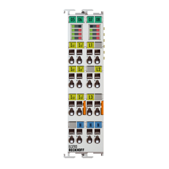
Beckhoff EL3783 Documentation (188 pages)
Power monitoring oversampling terminal for 690 V
Brand:
Beckhoff
| Category:
Touch terminals
| Size: 6 MB
Table of Contents
Table of Contents
3
Foreword
5
Notes on the Documentation
5
Safety Instructions
6
Documentation Issue Status
7
Version Identification of Ethercat Devices
7
Fig. 1 EL5021 el Terminal, Standard IP20 IO Device with Serial/ Batch Number and Revision ID (Since 2014/01)
9
Fig. 2 EK1100 Ethercat Coupler, Standard IP20 IO Device with Serial/ Batch Number
9
Fig. 3 CU2016 Switch with Serial/ Batch Number
9
Fig. 4 EL3202-0020 with Serial/ Batch Number 26131006 and Unique ID-Number 204418
10
Fig. 5 EP1258-00001 IP67 Ethercat Box with Batch Number/ Date Code 22090101 and Unique Se- Rial Number 158102
10
Fig. 6 EP1908-0002 IP67 Ethercat Safety Box with Batch Number/ Date Code 071201FF and Unique Serial Number 00346070
10
Fig. 7 EL2904 IP20 Safety Terminal with Batch Number/ Date Code 50110302 and Unique Serial Num- Ber 00331701
10
Fig. 8 ELM3604-0002 Terminal with Unique ID Number (QR Code) 100001051 and Serial/ Batch Num- Ber 44160201
11
Start
12
Product Overview
13
Introduction
13
Fig. 9 EL3783
13
Technical Data
14
Technology
15
Fig. 10 Voltages in Three-Phase Mains Supply of Central Europe
15
Basics Communication
17
Ethercat Basics
17
Ethercat Cabling - Wire-Bound
17
General Notes for Setting the Watchdog
18
Fig. 11 System Manager Current Calculation
18
Fig. 12 Ethercat Tab -> Advanced Settings -> Behavior -> Watchdog
19
Ethercat State Machine
20
Fig. 13 States of the Ethercat State Machine
21
Coe Interface
22
Fig. 14 "Coe Online " Tab
23
Fig. 15 Startup List in the Twincat System Manager
24
Fig. 16 Offline List
25
Fig. 17 Online List
25
Distributed Clock
27
Fig. 18 Spring Contacts of the Beckhoff I/O Components
28
Mounting and Wiring
28
Instructions for ESD Protection
28
Installation on Mounting Rails
29
Fig. 19 Attaching on Mounting Rail
29
Fig. 20 Disassembling of Terminal
30
Fig. 21 Power Contact on Left Side
31
Connection System
32
Fig. 22 Standard Wiring
32
Fig. 23 Pluggable Wiring
32
Fig. 24 High Density Terminals
33
Fig. 25 Mounting a Cable on a Terminal Connection
34
Positioning of Passive Terminals
36
Fig. 26 Correct Positioning
36
Fig. 27 Incorrect Positioning
36
Prescribed Installation Position
37
Fig. 28 Recommended Minimum Distances for Standard Installation Position
37
Leds and Connection
38
Fig. 29 EL3783
38
Fig. 30 Measurement in a 3-Phase, 4-Conductor Grid, Asymmetrical Load
40
Fig. 31 Measurement in a 3-Phase, 4-Conductor Grid with 3 Voltage Transformers, Asymmetrical Load
40
Fig. 32 Measurement in a 3-Phase, 3-Conductor Grid, Asymmetrical Load
41
Commissioning
42
Twinact
42
Twincat Quick Start
42
Fig. 33 Relationship between User Side (Commissioning) and Installation
43
Fig. 34 Control Configuration with Embedded PC, Input (EL1004) and Output (EL2008)
44
Fig. 35 Initial Twincat 2 User Interface
45
Fig. 36 Selection of the Target System
46
Fig. 37 Specify the PLC for Access by the Twincat System Manager: Selection of the Target System
46
Fig. 38 Select "Scan Devices
47
Fig. 39 Automatic Detection of I/O Devices: Selection the Devices to be Integrated
47
Fig. 40 Mapping of the Configuration in the Twincat 2 System Manager
48
Fig. 41 Reading of Individual Terminals Connected to a Device
48
Twincat Development Environment
67
General Notes - Ethercat Slave Application
99
Fig. 133 Default Target State in the Slave
104
Fig. 132 Default Behaviour of the System Manager
104
Fig. 134 PLC Function Blocks
105
Fig. 135 Illegally Exceeding the E-Bus Current
106
Fig. 136 Warning Message for Exceeding E-Bus Current
106
Basic Function Principles
107
Fig. 137 Opening the *. Tnzip Archive
108
Fig. 138 Search of the Existing HW Configuration for the Ethercat Configuration of the Example
108
Fig. 139 Switchover Characteristic, DYN0 - DYN3
110
Oversampling Terminals/Boxes and Twincat Scope
111
Twincat 3 Procedure
112
Fig. 140 Oversampling PDO of the El37Xx Series and in the Comparison with El31Xx
112
Fig. 141 Adding a Scope Project into an Already Existing Project
113
Fig. 142 Representation of a Created PLC Array Variable („Aui_Samples") to Link with Oversampling Pdos of EL3773
114
Fig. 143 Insertion of a Free Task
115
Fig. 144 Task Property "Create Symbols" Must be Activated
115
Fig. 145 Insertion of Variable "Var 1" Fitting to the Oversampling (-Factor)
116
Fig. 146 Set up the Link of the PLC Array Variable (Left: for the Last Preceding Paragraph Step 2A, Right: for the Last Preceding Paragraph Step 2B)
116
Fig. 147 Select the EL3773 PDO "L1 Voltage Samples" to Create a Link to the PLC Array Variable „Aui_Samples
116
Fig. 148 Selection of the Oversampling Variable with the Target Browser
117
Fig. 149 Appending the Variable "Aui_Samples" below "Axis" Within the Scope Project of the Solution Explorer
117
Fig. 150 Example of Recording a Sine Signal with 10 X Oversampling at 1 Ms Measurement Cycle Time
118
Fig. 151 Activation of the ADS Server of the Ethercat Device (Twincat 3)
119
Fig. 152 Direct Access to Pdos of the Terminal by Scopeview
119
Twincat 2 Procedure
120
Fig. 153 PLC Declaration
121
Fig. 154 PLC in the System Manager
121
Fig. 155 Add Variable Type
121
Fig. 156 Definition of the Variable Type
122
Fig. 157 Overview of Declared Types
122
Fig. 158 Linking
123
Fig. 159 Array Variables of an Oversampling Terminal
123
Fig. 160 Settings in the Additional Task
123
Fig. 161 Variable Browser up to the Array VAR152
124
Fig. 162 Addsymbol on the Array
124
Fig. 163 Channel Settings
124
Fig. 164 Activation of the Marks
125
Fig. 165 Illustration of a 10 X Oversampling Variable of the EL3751 by the Scope2
126
Fig. 166 Activation of the ADS Server of the Ethercat Device (Twincat 2)
127
Fig. 167 Direct Access of the Scope2 to the Terminal's Pdos
127
Fig. 168 Automatically Calculated Array Variable (Red) in the Scope2
128
Process Data
129
Fig. 169 Process Data Flow EL3783
129
Fig. 170 Linking of 2-Bit Variable to Additional Task
130
Fig. 171 User Settings and Vendor Calibration in the Coe Online Directory
131
Fig. 173 Process Image of the EL3783 in the Twincat System Manager
134
Fig. 174 EL3783 Selection Dialog "Predefined PDO Assignment
136
Fig. 172 EL3783 Selection Dialog "Predefined PDO Assignment
136
Object Description and Parameterization
138
Restore Object
138
Configuration Data
139
Input Data
140
Information and Diagnostic Data
140
Standard Objects
141
Notices on Analog Specifications
147
Full Scale Value (FSV)
147
Measuring Error/ Measurement Deviation
148
Temperature Coefficient Tk [Ppm/K]
148
Single-Ended/Differential Typification
150
Common-Mode Voltage and Reference Ground (Based on Differential Inputs)
155
Dielectric Strength
155
Temporal Aspects of Analog/Digital Conversion
156
Diagnosis
160
Diagnostics - Basic Principles of Diag Messages
160
Firmware Update El/Es/Em/Elm/Epxxxx
170
Appendix
170
Device Description ESI File/Xml
171
Firmware Explanation
174
Updating Controller Firmware *.Efw
175
FPGA Firmware *.Rbf
176
Simultaneous Updating of Several Ethercat Devices
180
Firmware Compatibility
181
Restoring the Delivery State
181
Support and Service
182
List of Illustrations
184
Advertisement
Advertisement
Related Products
BECKHOFF EL3702
Beckhoff EL3773
beckhoff EL3111
beckhoff EL3112-0011
beckhoff EL3124
beckhoff EL3124-0090
beckhoff EL3141-0000
Beckhoff EL3443-0013
Beckhoff EL3483-0060
Beckhoff EL3443-0011
Beckhoff Categories
Touch terminals
Industrial PC
Control Unit
Industrial Equipment
Control Panel
More Beckhoff Manuals
Login
Sign In
OR
Sign in with Facebook
Sign in with Google
Upload manual
Upload from disk
Upload from URL