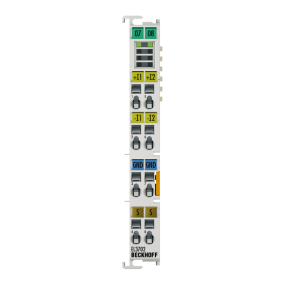
Sign In
Upload
Manuals
Brands
BECKHOFF Manuals
Touch terminals
EL3702
BECKHOFF EL3702 Manuals
Manuals and User Guides for BECKHOFF EL3702. We have
1
BECKHOFF EL3702 manual available for free PDF download: Documentation
BECKHOFF EL3702 Documentation (181 pages)
EL37x2 series Analog Input Terminals with oversampling
Brand:
BECKHOFF
| Category:
Touch terminals
| Size: 6.85 MB
Table of Contents
Table of Contents
4
1 Product Overview Analog Input Terminals with Oversampling
3
Table of Contents
4
2 Foreword
7
Notes on the Documentation
7
Safety Instructions
8
Documentation Issue Status
9
Version Identification of Ethercat Devices
9
Fig. 1 EL5021 el Terminal, Standard IP20 IO Device with Batch Number and Revision ID (Since 2014/01)
11
Fig. 2 EK1100 Ethercat Coupler, Standard IP20 IO Device with Batch Number
11
Fig. 3 CU2016 Switch with Batch Number
12
Fig. 4 EL3202-0020 with Batch Numbers 26131006 and Unique ID-Number 204418
12
Fig. 5 EP1258-00001 IP67 Ethercat Box with Batch Number 22090101 and Unique Serial Number 158102
12
Fig. 6 EP1908-0002 IP67 Ethercat Safety Box with Batch Number 071201FF and Unique Serial Number 00346070
12
Fig. 7 EL2904 IP20 Safety Terminal with Batch Number/Date Code 50110302 and Unique Serial Num- Ber 00331701
13
Fig. 8 ELM3604-0002 Terminal with ID Number (QR Code) 100001051 and Unique Serial Number 44160201
13
3 Product Overview
14
EL3702 - Introduction
14
EL3702 - Technical Data
15
EL3742 - Introduction
16
EL3742 - Technical Data
17
Basic Function Principles
18
Fig. 11 Optional Process Record Starttimenextlatch
20
Fig. 12 Temporal Relationship between SYNC Signals and Syncmanager Interrupt
21
Sample Programs
22
Fig. 13 Connection for Sample Program
23
Fig. 14 Searching the Ethernet Adapter
24
Fig. 15 Selection and Confirmation of the Ethernet Adapter
24
Fig. 16 Activation of the Configuration
24
Fig. 17 Confirming the Activation of the Configuration
24
Fig. 18 Generating Variable Mapping
25
Fig. 19 Restarting Twincat in RUN Mode
25
Fig. 20 Compile Project
25
Fig. 21 Confirming Program Start
25
4 Basics Communication
27
Ethercat Basics
27
Ethercat Cabling - Wire-Bound
27
General Notes for Setting the Watchdog
28
Fig. 22 System Manager Current Calculation
28
Fig. 23 Ethercat Tab -> Advanced Settings -> Behavior -> Watchdog
29
Ethercat State Machine
30
Fig. 24 States of the Ethercat State Machine
31
Coe - Interface: Notes
32
Distributed Clock
33
5 Mounting and Wiring
34
Instructions for ESD Protection
34
Installation on Mounting Rails
34
Fig. 25 Spring Contacts of the Beckhoff I/O Components
34
Fig. 26 Attaching on Mounting Rail
35
Fig. 27 Disassembling of Terminal
36
Installation Instructions for Enhanced Mechanical Load Capacity
37
Fig. 28 Power Contact on Left Side
37
Connection System
38
Fig. 29 Standard Wiring
38
Fig. 30 Pluggable Wiring
39
Fig. 31 High Density Terminals
39
Fig. 32 Mounting a Cable on a Terminal Connection
40
Installation Positions
41
Fig. 33 Recommended Distances for Standard Installation Position
41
Fig. 34 Other Installation Positions
42
Mounting of Passive Terminals
43
Fig. 35 Correct Configuration
43
Fig. 36 Incorrect Configuration
43
ATEX - Special Conditions (Extended Temperature Range)
44
ATEX Documentation
45
UL Notice
45
Configuration of 0/4
47
Fig. 37 Internal Connection 0/4
47
Fig. 38 Internal Connections for 0/4
48
Fig. 39 Example 1: Low-Side Measurement
48
Fig. 40 Example 1A, High-Side Measurement
49
Fig. 41 Example 2, High-Side/Low-Side Measurement
49
El37X2 - Leds and Pin Assignment
51
El37X2 - Leds
51
El37X2 - Pin Assignment
52
6 Commissioning
55
Twincat Quick Start
55
Twincat 2
79
Twincat 3
79
Twincat Development Environment
79
Installation of the Twincat Real-Time Driver
79
Notes Regarding ESI Device Description
85
Twincat ESI Updater
89
Distinction between Online and Offline
89
OFFLINE Configuration Creation
90
ONLINE Configuration Creation
95
Fig. 132 Twincat 2 Dialog Change to Alternative Type
102
Ethercat Subscriber Configuration
103
Fig. 133 Branch Element as Terminal EL3751
103
Fig. 134 "General" Tab
103
Fig. 135 „Ethercat" Tab
104
Fig. 136 "Process Data" Tab
105
Fig. 137 Configuring the Process Data
106
Fig. 138 „Startup" Tab
107
Fig. 139 "Coe - Online" Tab
108
Fig. 140 Dialog "Advanced Settings
109
Fig. 141 „Online" Tab
110
Fig. 142 "DC" Tab (Distributed Clocks)
111
General Notes - Ethercat Slave Application
113
Fig. 143 Selection of the Diagnostic Information of an Ethercat Slave
113
Fig. 144 Basic Ethercat Slave Diagnosis in the PLC
114
Fig. 145 EL3102, Coe Directory
116
Fig. 146 Example of Commissioning Aid for a EL3204
117
Fig. 147 Default Behaviour of the System Manager
118
Fig. 148 Default Target State in the Slave
118
Fig. 149 PLC Function Blocks
119
Fig. 150 Illegally Exceeding the E-Bus Current
120
Fig. 151 Warning Message for Exceeding E-Bus Current
120
Oversampling Terminals and Twincat Scope
121
Fig. 152 Oversampling PDO of the El37Xx Series and in the Comparison with El31Xx
121
Twincat 3 Procedure
122
Fig. 153 Adding a Scope Project into an Already Existing Project
123
Fig. 154 Representation of a Created PLC Array Variable („Aui_Samples") to Link with Oversampling Pdos of EL3773
124
Fig. 155 Insertion of a Free Task
124
Fig. 156 Task Property "Create Symbols" Must be Activated
125
Fig. 157 Insertion of Variable "Var 1" Fitting to the Oversampling (-Factor)
125
Fig. 158 Set up the Link of the PLC Array Variable (Left: for the Last Preceding Paragraph Step 2A, Right: for the Last Preceding Paragraph Step 2B)
126
Fig. 159 Select the EL3773 PDO "L1 Voltage Samples" to Create a Link to the PLC Array Variable „Aui_Samples
126
Fig. 160 Selection of the Oversampling Variable with the Target Browser
127
Fig. 161 Appending the Variable "Aui_Samples" below "Axis" Within the Scope Project of the Solution Explorer
127
Fig. 162 Example of Recording a Sine Signal with 10 X Oversampling at 1 Ms Measurement Cycle Time
128
Fig. 163 Activation of the ADS Server of the Ethercat Device (Twincat 3)
129
Fig. 164 Direct Access to Pdos of the Terminal by Scopeview
129
Twincat 2 Procedure
130
Fig. 165 PLC Declaration
131
Fig. 166 PLC in the System Manager
131
Fig. 167 Add Variable Type
131
Fig. 168 Definition of the Variable Type
132
Fig. 169 Overview of Declared Types
132
Fig. 170 Linking
133
Fig. 171 Array Variables of an Oversampling Terminal
133
Fig. 172 Settings in the Additional Task
133
Fig. 173 Variable Browser up to the Array VAR152
134
Fig. 174 Addsymbol on the Array
134
Process Data and Configuration
139
Twincat Tree
139
Extent of Process Data in Delivery State
141
Oversampling Settings, Distributed Clocks (DC)
145
Notices on Analog Specifications
151
Full Scale Value (FSV)
152
Measuring Error/ Measurement Deviation
152
Temperature Coefficient Tk [Ppm/K]
153
Single-Ended/Differential Typification
154
Common-Mode Voltage and Reference Ground (Based on Differential Inputs)
159
Dielectric Strength
159
Temporal Aspects of Analog/Digital Conversion
160
7 Appendix
164
Ethercat al Status Codes
164
Firmware Information for El37Xx/El47Xx
164
Firmware Compatibility
165
Firmware Update El/Es/Em/Epxxxx
165
Support and Service
176
List of Illustrations
177
Advertisement
Advertisement
Related Products
Beckhoff EL3773
Beckhoff EL3783
beckhoff EL3102
beckhoff EL3112
beckhoff EL3122
Beckhoff EL34x3 Series
Beckhoff EL3413-0000
Beckhoff EL34 Series
Beckhoff EL3453
Beckhoff EL3632
BECKHOFF Categories
Touch terminals
Industrial PC
Control Unit
Touch Panel
Power Supply
More BECKHOFF Manuals
Login
Sign In
OR
Sign in with Facebook
Sign in with Google
Upload manual
Upload from disk
Upload from URL