Sign In
Upload
Manuals
Brands
Bang & Olufsen Manuals
CD Player
BeoSound 9000 MKIII
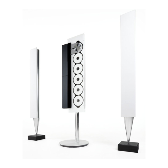
Bang & Olufsen BeoSound 9000 MKIII Manuals
Manuals and User Guides for Bang & Olufsen BeoSound 9000 MKIII. We have
2
Bang & Olufsen BeoSound 9000 MKIII manuals available for free PDF download: Service Manual
Bang & Olufsen BeoSound 9000 MKIII Service Manual (97 pages)
Brand:
Bang & Olufsen
| Category:
CD Player
| Size: 4.78 MB
Table of Contents
Table of Contents
2
Specification Guidelines for Service Use
3
Connections
4
Headphone
4
Dimensions
5
Optional Accessories
5
Brief Operation Guide
6
Closeup Operation
6
Loading Cds
6
CD Playback
6
Mono/Stereo Reception
7
Fine Tuning a Radio Station
7
Presetting Radio Stations
7
Playing Your Radio Programs
7
Checking or Clearing Timers
8
Setting and Using the Built-In Clock
8
Option Programming Beo4
8
Option Programming Beolink 1000
8
The PIN-Code System
9
Activate the PIN-Code System
9
Change or Delete Your PIN-Code
9
Using Your PIN-Code
9
Wiring Connections
10
Explanation of Diagram
10
Control Circuit
10
Component Print and Coordinate System
10
Measuring Conditions
11
Caution
11
CD Laserdiode
11
Lithium Battery
11
Wiring Diagram
12
Overall Block Diagram
13
Block Diagram for am
14
Block Diagram for Frontend Tuner
14
Block Diagram for CD
15
Block Diagram for Input/Output Select
16
Block Diagram for Data
17
Block Diagram for Motor Control
18
Block Diagram for Power Supply
19
PCB Drawing for PCB1
20
FM/AM Detector
21
DIAGRAM B – Stereo Decoder and Power Section
22
DIAGRAM BB – RDS and Μp
23
PCB1, FM/AM - RDS – Primary Side
24
DIAGRAM C – CD Servo Decoder
25
DIAGRAM D – Turn Table and Motor Control
26
PCB41, CD – Primary Side
26
PCB41, CD – Secondary Side
26
DIAGRAM E – Master Link Interface Data/Audio
27
DIAGRAM F – Digital/Analog Decoder
28
DIAGRAM G – Input Select and Sound Adjustment
29
PCB21, Headphone
30
PCB32, Input/Output Select, Sound Adjustment – Preliminary Side
30
PCB32, Input/Output Select, Sound Adjustment – Secondary Side
30
PCB Drawing for PCB14
31
PCB13, Secondary Keyboard
31
DIAGRAM H – Keyboard and IR Receiver
31
DIAGRAM I – Display and Clamper Position
32
PCB22, Clamper Position
32
DIAGRAM J – Microcomputer, Power Supply & Light Indicator
33
PCB34, Power Supply
34
DIAGRAM L – Motor Control
35
PCB35, Motor Control
36
PCB28, Safety RX
37
PCB37, Lid Motor
37
PCB26, End Stop Detector
37
PCB9, Sledge Position
37
DIAGRAM N – Power Supply
38
DIAGRAM O – Mains Relay USA
39
PCB14, IR Receiver
39
PCB24, Light Indication, Left
39
PCB5, Mains Relay
39
PCB4, Mains Filter
40
PCB7, Display
40
List of Electrical Parts
41
Light Indication, Left
45
Light Indication, Right
45
End Stop Detector
45
Lamp
45
IR Transmitter, Tacho Clamper
45
IR Reciever, Tacho Clamper
45
Input/Output Select, Sound Adj
45
Power Supply
47
List of Mechanical Parts
56
Guide F/Wire and Ribbon Cables
61
Bracket 2053
63
Wall Bracket Horizontal 2054
64
Wall Bracket Vertical 2063
65
Adjustable in Two Heights
66
Stand 2065
66
Adjustment of Sensitivity of Fi Nger Protection System
67
Adjustments
67
Mechanical Adjustments
68
Adjustment of CD Mechanism
68
Adjustment of Lid
68
Adjustment of Clamper Arm
68
Tuner Test Modes
69
Master Test Modes
69
TM (Test Mode) Names/Function for Adjustments and Service
69
Test Modes
69
Test Mode Activating (by Beo4)
70
Deactivating Test Mode (by Beo4)
70
Tm01
70
Tm02
70
Tm07
71
Tm20
71
Tm21
71
Tm22
71
Tm27
72
Tm25
72
Tm24
72
Tm23
72
Tm28
77
Tm31
77
Tm32
77
Tm34
77
Tm36
78
Tm61
78
Tm62
78
Tm63
78
Glass Doors Lock
79
Tm73
79
Tm74
79
Tm72
79
Theft Protection
80
Service Code
80
Master Code
80
How to Order Master Code
80
Exchange of Software EEPROM on PCB3
81
Exchange of both Micro-Processor Module PCB3 and Software EEPROM on PCB3
81
Set and Enter PIN Code
81
Activate the PIN Code System
81
Change PIN Code
82
If You Have Forgotten Your PIN Code
82
Deactivate the PIN Code System
82
Replacement of Components
83
Exchange of Microprocessor Module PCB3
83
Replacement of 7DP1, 7DP2 or 7DP3
83
Replacement of 29IL1 and 7IL1
83
Repair Tips
84
Voltage to Sledge Motor
84
Repair of Autopositioning
84
Why Does the Product Not Work?
84
Miscellaneous
85
Glass Lid
85
Sledge
85
Reading Guide
86
Motor Control
86
Dismantling and Assembly
88
Access to the Individual Modules
88
PCB1 FM/AM, RF if Decoder
88
PCB3 Main Microcomputer
88
PCB5 Mains Relay
89
PCB7 Display
89
PCB9 Sledge Position
89
PCB11 Main Keyboard, Left
89
PCB28 Safety RX
90
PCB24 Light Indication Right
90
PCB25 Light Indication Left
90
PCB26 End Stop Detector
90
Mechanical/Electrical Dismantling
91
PCB34 Microcomputer and Power Supply
91
PCB35 Motor Control
91
Pcb41 CD
91
Lid Motor
91
Left Aluminium Plate (Grooved Profile)
92
Release of Sledge
92
Cover for Chassis Top Plate
92
Clamper Arm
93
Chassis Top Plate
93
Top Plate for CD Mechanism
93
Cover for CD Clamper
93
CD Mechanism
94
Top Plate
94
Sledge and Ribbon Cables
95
Sledge Motor and Wire Drive
95
Gearbox
95
Rear Panel
95
Insulation Test
96
Advertisement
Bang & Olufsen BeoSound 9000 MKIII Service Manual (97 pages)
Brand:
Bang & Olufsen
| Category:
Speakers
| Size: 4.76 MB
Advertisement
Related Products
BANG & OLUFSEN BEOSOUND 9000
Bang & Olufsen BeoSound 3000
Bang & Olufsen Beogram 9000 5961
Bang & Olufsen Beogram 9000 5963
Bang & Olufsen Beogram 9000 5964
Bang & Olufsen Beogram 9000 5965
Bang & Olufsen BeoLab 9
Bang & Olufsen Beogram 9500 5966
Bang & Olufsen Beogram 9500 5968
Bang & Olufsen 9699
Bang & Olufsen Categories
Speakers
Headphone
TV
Stereo System
Remote Control
More Bang & Olufsen Manuals
Login
Sign In
OR
Sign in with Facebook
Sign in with Google
Upload manual
Upload from disk
Upload from URL