Sign In
Upload
Manuals
Brands
Automatic Systems Manuals
Other
TRS 372
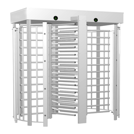
Automatic Systems TRS 372 Turnstile Manuals
Manuals and User Guides for Automatic Systems TRS 372 Turnstile. We have
2
Automatic Systems TRS 372 Turnstile manuals available for free PDF download: Technical Manual, Technical Instructions
Automatic Systems TRS 372 Technical Manual (62 pages)
Security Turnstile
Brand:
Automatic Systems
| Category:
Turnstiles
| Size: 15 MB
Table of Contents
Table of Contents
3
Introduction
6
Safety Warnings
7
Overview of Symbols Used
8
Terminology
9
Description
10
Overall Dimensions
10
Fig. 1 - Overall Dimensions
10
Conventions
11
Fig. 2 - Conventions for Directions A/B and Directions C/D
11
Technical Features
12
Location of Components
13
External Components
13
Fig. 3 - External Components
13
Internal Components
14
Electrical/Electronic Components
14
Fig. 4 - Internal Components
14
Fig. 5 - Detail of Electronic Logic Board
14
Operation
15
Operating Principle (Modes 3 and 5)
15
Fig. 6 - Mechanical Assembly
15
Operating Principle (Mode 4)
16
Mode of Operation When Switched off
16
Mode of Operation in the Directions of Passage
16
Card Reader Mode
16
Pulse Mode
16
Maintained Mode
16
Mixed Mode
16
Illuminated Signage
17
Orientation Pictograms
17
Function Pictograms
18
Box for Card Reader Integration (Optional)
19
Fig. 7 - Box for Card Reader Integration
19
Fig. 8 - Small Box Dimensions
19
Fig. 9 - Large Box Dimensions
19
Installation
20
Packaging
20
Fig. 10 - Sub-Assemblies Included in the TRS Package
20
Unpacking
21
Recommended Installation Tools
21
Switching the Equipment on and off
21
Fig. 11 - Switching the Equipment on and off
21
Installation Diagrams
22
Mounting on a Finished Floor
23
Fig. 12 - Installation Diagram - Mounting on a Finished Floor
23
Mounting on a Fixing Frame
24
Fig. 13 - Installation Diagram - Mounting on a Fixing Frame
24
Drilling Template (Standard) or Fixing Frame (Optional)
25
Fig. 14 - Drilling Template for Finished Floors (GAB-E-0007770 & GAB-E-0007773)
25
Fig. 15 - Optional Fixing Frame
25
Procedure for Installation on a Finished Floor
26
Preparing for Installation on a Finished Floor
26
Fig. 16 - Drilling Templates - Drawing the Main Axes (Step 1)
26
Fig. 17 - Drilling Templates - Plotting the Attachment Points for the Curved Parts (Step 2)
27
Fig. 18 - Drilling Templates - Plotting the Attachment Points for the Curved Parts (Step 3)
27
Fig. 19 - Recommended Bore for Expansion Bolt Model B15/13 Supplied by Automatic Systems
28
Assembling the Curved Parts
29
Fig. 20 - Assembling the Curved Parts
29
Assembling the Centre Uprights
30
Fig. 21 - Assembling the Curved Parts
30
Fitting the Upright Protectors and Caps
31
Fig. 22 - Fitting the Upright Protectors and Caps
31
Installing the Curved Parts and Centre Uprights with the Mounting Kit for Finished Floors
32
Fig. 23 - Installation with Mounting Kit on a Finished Floor
32
Assembling the Fixed Combs on the Centre Uprights
33
Fig. 24 - Assembling the Fixed Combs on the Centre Uprights
33
Mounting the Head Unit
34
Fig. 25 - Attaching the Head Unit with the Curved Parts
34
Fig. 26 - Attaching the Head Unit to the Centre Uprights
35
Fitting the Lower Axle for the Mobile Obstacle
36
Fitting the Bottom Flange
36
Fig. 27 - Fitting the Lower Axle for the Mobile Obstacle
36
Fig. 28 - Fitting the Bottom Flange for the Mobile Obstacle
36
Fitting the Mobile Obstacle
37
Fig. 29 - Mobile Comb Closest to the Floor
37
Fig. 30 - Mobile Comb Furthest from the Floor
37
Fig. 31 - Fitting the Mobile Combs
38
Fig. 32 - Fitting the Caps on the Mobile Combs
38
Heel Guard Assembly (Option)
39
Mounting the Roof
40
Installing / Removing the Door
40
Fig. 33 - Mounting the Roof
40
Fig. 34 - Installing the Door
40
Fig. 35 - Removing the Door
40
Installation Procedure with Fixing Frame (Optional)
41
Preparing for Installation with a Fixing Frame
41
Fig. 36 - Shaft Dimensions
41
Fig. 37 - Assembling the Fixing Frame (GBR-E-0004248)
41
Fig. 38 - Centre Distance for the Fixing Frame
42
Fig. 39 - Positioning the Fixing Frame in the Shaft
43
Fig. 40 - Installing the Fixing Frame - Concrete
43
Installation on the Optional Fixing Frame
44
Fig. 41 - Fitting the Bottom Flange for the Mobile Obstacle
44
Installation of Optional Equipment
45
Attaching the Canopies (Optional)
45
Fig. 42 - Drilling the Head Unit to Attach the Canopies
45
Fig. 43 - Silicone Sealant Bead on Installation Surface
45
Fig. 44 - Silicone Sealant Bead Around Connecting Edge
45
Mounting the Card Reader Box(Es) (Optional)
46
Fig. 45 - Mounting the Card Reader Box
46
Electrical Connections
47
Fig. 46 - Electrical Connections
47
Maintenance
48
Replacing an Electromagnet or Reversing Its Direction
48
Fig. 47 - Mode of Operation 5
48
Fig. 48 - Mode of Operation 4
48
Fig. 49 - Change of Mode / Replacement of an Electromagnet
49
Replacing the Shock Absorber
50
Replacing the Angle Sensor Assembly
50
Fig. 50 - Mounting the Shock Absorber
50
Fig. 51 - Replacing the Angle Sensor Assembly
50
Replacing Bushings, Springs and Other Wear Parts
51
Replacing an Orientation Pictogram
51
Service
52
Spare Parts
53
Troubleshooting
54
Extended Shutdown / Disposal / Destruction
55
Description of the Electronic Assembly
56
AS1635 Motherboard
56
Fig. 52 - AS1635 Motherboard
56
Electrical Diagrams
58
Click here
58
Declaration of Conformity
59
Fig. 53 - CE Declaration
59
Advertisement
Automatic Systems TRS 372 Technical Instructions (38 pages)
Brand:
Automatic Systems
| Category:
Other
| Size: 2 MB
Table of Contents
Table of Contents
3
1 Safety Warnings
4
2 Installation
5
Equipment Storage before Installation
5
List of Tools Required
5
Installation on Finished Ground Surface (with Template)
6
Installation with Fixing Frame (Option)
8
Turnstile Assembly
10
Fixed Panel Assembly
10
Central Upright Assembly
11
Plugs Installation
12
Fixing the Turnstile to the Ground
13
Upper Box Section Assembly
14
Canopy Assembly (Option)
15
Mobile Comb Assembly
16
Heel Guard Assembly (Option)
17
Electrical Connections
17
3 Description
18
Technical Specifications
18
Operating Modes
18
Mode Descriptions
18
Power Failure
18
Location of the Components
19
Fixed Panel
20
Mobile Combs
20
Fixed Combs
21
Upper Box
22
Heating Resistance (Option)
23
Mechanical Assembly
24
Modes 3 and 5 - Operating Principle
25
Mode 4 - Operating Principle
25
Pictograms
26
Orientation Pictograms
26
Function Pictograms
26
Control Board
27
4 Maintenance
34
5 Troubleshooting
35
6 Electrical Diagrams
36
Control Board Terminal Block Assignment
37
Nam-Trs372-Mt-En-C
37
Advertisement
Related Products
automatic systems TR490
Automatic Systems TRS373
Automatic Systems TriLane TL Series
Automatic Systems TriLane TL1
Automatic Systems TriLane TL2
Automatic Systems TBV327
Automatic Systems TR491
Automatic Systems TR450
Automatic Systems TRILANE TL2P
Automatic Systems PNG380
Automatic Systems Categories
Turnstiles
Security System
Control Systems
Computer Hardware
Automatic Barriers
More Automatic Systems Manuals
Login
Sign In
OR
Sign in with Facebook
Sign in with Google
Upload manual
Upload from disk
Upload from URL