Sign In
Upload
Manuals
Brands
Audi Manuals
Automobile
A8 1994
Audi A8 1994 Manuals
Manuals and User Guides for Audi A8 1994. We have
5
Audi A8 1994 manuals available for free PDF download: Repair Manual, Service Manual, Body Repair Manual
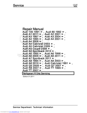
Audi A8 1994 Repair Manual (211 pages)
Vehicle air conditioning systems
Brand:
Audi
| Category:
Air Conditioner
| Size: 1.94 MB
Table of Contents
Table of Contents
3
General, Technical Data
5
1 General Information
5
A/C System
5
Refrigerant Oil
11
Safety Precautions
12
Laws and Regulations
16
A/C System Principles
22
1.4 Refrigerant Circuit and Components
25
Refrigerant Circuit and Components
25
Component Replacement
26
Connections for Quick-Release Coupling on Refriger- Ant Circuit
28
O-Ring Seals
28
Refrigerant Circuit Connections with Valve for Switches
30
Refrigerant Circuit Pipes and Hoses
30
Refrigerant Circuit, Cleaning
31
Refrigerant Circuit, Converting R12 to R134A
31
Refrigerant Circuit, Flushing
32
Refrigerant Circuit Flushing with Compressed Air and Nitrogen
33
Refrigerant Circuit Flushing with Refrigerant R134A
36
Refrigerant Circuit, Repairing
43
Switches and Sensors
43
2 Description and Operation
45
Refrigerant Circuit
45
Refrigerant Circuit Precautions
45
Ball Valve
63
Pressure Relief Valve
72
Switches and Sensors on Refrigerant Circuit and Connections
78
Electrical Components Not on Refrigerant Circuit
82
2.4 A/C Service Station
83
A/C Service Station
83
Using Service Station
84
Charging Refrigerant Circuit
87
Connecting for Measuring and Testing, Two Service Connections
87
Connecting for Measuring and Testing, One Service Connection
88
Connecting for Measuring and Testing, no Service Connection
89
Connecting with Air Conditioning Adapter Set V.A.G 1786
90
Connecting with Adapter Set VAG1785/10
91
Draining Refrigerant Circuit
91
Draining Service Station
92
Evacuating Refrigerant Circuit
93
Transferring Refrigerant to Reservoir (Charging Cylinder or Reservoir Bottle) of Service Station
97
3 Specifications
98
Charging Refrigerant
98
Refrigerant R134A Capacities
98
Capacities, Audi A3 (8L_) 1997 through MY 2004 and Audi TT (8N_), from MY 1999
100
Capacities, Audi A3 (8P_) from MY 04
103
Capacities, Audi TT (8J_) from MY 07
104
Capacities, Audi 80 (8A_/8C_), Audi Coupe (8B_) and Audi Cabriolet (8G_), from MY 2002
105
Capacities, Audi A4 (8D_), from MY 95
105
Audi A5 Cabriolet (8F_) from MY 2009
109
Capacities, Audi A4 (8K_) from MY 2008, Audi A5
109
Capacities, Audi 100 and Audi A6 (4A_), from MY 98
110
Capacities, Audi A6 (4B_) from MY 1998 and Audi Allroad (4B_) from MY 2005
111
Capacities, Audi A6 (4F_), from MY 05
116
Capacities, Audi V8 (4C_) from MY 94
117
Capacities, Audi A8 (4D_) from MY 94
118
Capacities, Audi A8 (4E_) from MY 03
119
Capacities, Audi A8 (4H_) from MY 10
119
Features of the Refrigerant System
119
Refrigerant Oils
121
3.4 Refrigerant Oil Capacities
123
Refrigerant Oil Capacities
123
At Start of Production, A/C Compressors Manufactured by
125
Led. Refer to Electronic Parts Catalog (ETKA) and ⇒ Heating
125
Ventilation and Air Conditioning; Rep. Gr. 87 ; Removal and
125
Depending on the Engine, an A/C Compressor Manufactured
125
Time (Introduction Still Open). Refer to Electronic Parts Catalog
125
(ETKA) and ⇒ Heating, Ventilation and Air Conditioning; Rep
125
Gr. 87 ; Removal and Installation
125
Capacities, Audi A2 (8Z_) from MY 01
125
Restrictor (Colored)
125
Removal and Installation
126
Capacities, Audi A3 (8L_) 1997 through MY 2004 and Audi TT (8N_), from MY 1999
126
Capacities, Audi A3 (8P_) from MY 04
127
Capacities, Audi TT (8J_) from MY 07
128
Capacities, Audi 80 (8A_/8C_), Audi Coupe (8B_) and Audi Cabriolet (8G_), from MY 2002
129
3.4.7 Capacities, Audi A4 (8D_), from My 95
130
Vehicle Mod-Production Period Total Quantity of Oil in Refrig-Quantity of Refrigerant Oil in Replace- el Erant Circuit in CM 3 Ment Compressor in CM
133
As of 04.97
134
The Replacement Compressor Contains the Full Quantity of Oil
134
Intended for the Refrigerant Circuit. on A/C Compressor Re
134
Placement, the Quantity of Oil in the A/C Compressor Is There
134
Fore to be Adjusted. Refer to
134
Beginning the Production Year 2006, the Name of the Zexel a
134
C Compressor was Changed from Zexel to Valeo
134
Vehicle Mod-Production Period Total Quantity of Oil in Refrig-Quantity of Refrigerant Oil in Replace- el Erant Circuit in CM 3 Ment Compressor in CM
136
As of
141
4 Diagnosis and Testing
146
Pressure Gauge, Tests and Measurements
146
Leak Detection
147
Refrigerant Circuit Concerns
155
Pressures, Checking
157
5 Removal and Installation
195
Leaking or Damaged Components Except A/C Compressor, Accumulator or Receiver - Circuit Empty of Refrigerant
195
Leaking or Damaged Components Except A/C Compressor, Accumulator or Receiver - Circuit Contains Refrigerant
197
Compressor, Replacing Without Flushing Refrigerant Circuit
197
Compressor, Replacing Due to Leakage or Internal Damage
198
Receiver or Accumulator and Restrictor, Replacing after Cleaning Refrigerant Circuit
199
Receiver or Accumulator, Replacing Without Flushing Refrigerant Circuit
200
Dryer Cartridge and Dryer Bag, Replacing Without Flushing Refrigerant Circuit
201
6 Special Tools
202
Commercially Available Tools and Materials
202
Improvised Tools
207
Advertisement
Audi A8 1994 Service Manual (168 pages)
Brand:
Audi
| Category:
Automobile
| Size: 1.18 MB
Table of Contents
Table of Contents
3
Self-Diagnosis
5
Dash Panel Insert Self-Diagnosis with Service Interval Extension
5
General Information
5
Starting Dash Panel Insert Self-Diagnosis
6
Interrogate Fault Memory
8
Fault Table
9
Final Control Diagnosis
16
Erase Fault Memory
19
End Output
21
Code Control Unit
21
Read Measured Value Block
24
Adaption
32
Adaption Channels 02 to 09
38
Adaption Channels 18 to 33
46
Adaption Channels 40 to 48
52
Adaption Channels 60 to 62
66
With Respect to the Correctness of Information in this Document. Copyright by AUDI AG
67
Input Values on Dash Panel Insert Replacement
71
Resetting Service Display on Completion of Service Work (Without VAS 5051)
72
Checking Data Exchange between Control Units
73
Immobilizer Self-Diagnosis - Immobilizer III
76
General Information
76
Starting Immobilizer Self-Diagnosis
78
Interrogate Fault Memory
80
Fault Table
81
Erase Fault Memory
82
End Output
84
Read Measured Value Block
84
Adaption
88
Matching of Vehicle Keys
88
Procedure in the Event of Loss of Keys
94
Adaption Following Replacement of Dash Panel Insert
95
Adaption Following Replacement of Engine Control Unit
100
Adaption Following Replacement of Dash Panel Insert and Engine Control Unit
104
Control Unit Release
108
Cruise Control System (CCS) Self-Diagnosis
111
General Information
111
Checking Cruise Control System (CCS) - Petrol Engines with Electronic Throttle
111
Checking Cruise Control System (CCS) - Diesel Engines
116
Wiring and Component Check Using Test Box V.A.G 1598/31
119
Activating/Deactivating Cruise Control System
120
Acoustic Parking System (APS) Self-Diagnosis
122
General Information
122
Starting Automatic Parking System Self-Diagnosis
122
Interrogate Fault Memory
124
Fault Table
125
Final Control Diagnosis
130
Erase Fault Memory
132
End Output
133
Code Control Unit
134
Read Measured Value Block
136
Adaption
140
Automatic Headlight Range Control Self-Diagnosis
149
General Information
149
Starting Automatic Headlight Range Control Self-Diagnosis
150
Interrogate Fault Memory
151
Fault Table
153
Final Control Diagnosis
155
Basic Setting
157
Erase Fault Memory
159
End Output
160
Code Control Unit
161
Read Measured Value Block
163
Connecting Vehicle Diagnostic, Testing and Information System VAS 5051
166
Safety Precautions
166
Audi A8 1994 Service Manual (113 pages)
Motronic injection and ignition system (6-cylinder)
Brand:
Audi
| Category:
Automobile
| Size: 1.2 MB
Table of Contents
Table of Contents
3
Self-Diagnosis of Motronic System
5
Technical Data for Self-Diagnosis
5
Self-Diagnosis
5
Connecting Vehicle Diagnostic, Testing and Information System VAS 5051 or Fault Reader V.A.G 1551 and Selecting Functions
6
Interrogating and Erasing Fault Memory
8
Fault Table
9
Final Control Diagnosis
19
Basic Setting
21
Coding Control Unit
23
Reading Measured Value Block
25
Rules for Cleanliness
26
Mixture Preparation, Injection
26
Safety Precautions
26
Servicing Motronic Injection System
26
Technical Data
27
Fitting Locations Overview
27
Dismantling and Assembling Fuel Rail with Injectors
32
Removing and Installing Parts of Intake Manifold Change-Over
33
Wiring and Component Check with Test Box V.A.G 1598/31
34
Renewing Engine Control Unit -J220
35
Section 1
36
Testing Idling Speed
37
Checking Fuel Pressure Regulator and Holding Pressure
38
Perform Adaption of Throttle Valve Control Part (J338) => Page
38
Checking Injectors
40
Testing Injection Quantity, Leak-Tightness and Spray Pattern of Injectors
44
Select Engine Electronics Control Unit by Entering Address Word "01
46
Testing Fuel Pump Relay -J17 and Relay Activation
46
When Doing this the Ignition Must be Switched on
46
Indicated on Display
49
Rapid Data Transfer HELP Select Function
49
Select Engine Electronics Control Unit by Entering Address Word "01
49
Testing Air Mass Meter -G70
49
Checking Intake Air System for Leaks (Unmetered Air)
52
Testing Intake Air Temperature Sender -G42
53
Testing Coolant Temperature Sender-G62
55
Operation of Lambda Control
56
Testing Lambda Control
56
Testing Lambda Probe and Lambda Control
57
Testing Lambda Probe Heating
61
Testing Lambda Probe Signal Wiring and Activation
64
Removing and Installing Lambda Probe
67
Testing Intake Manifold Change-Over Function
67
Testing Operation
67
Testing Intake Manifold Change-Over Valve -N156
68
Testing Vacuum System
71
Testing Secondary Air Inlet Valve
72
Testing Secondary Air System
72
Testing Secondary Air Pump Relay -J299
74
Testing Fuel Tank Breather System
76
Testing Solenoid Valve 1 for Activated Charcoal Filter -N80
76
Operation of Electronic Throttle System
80
Performing Adaption of Throttle Valve Control Part
80
Testing Electronic Engine Power Control (Electronic Throttle)
80
Testing Throttle Valve Control Part -J338
80
Testing Angle Senders for Throttle Valve Drive
83
Notes on EPC Warning Lamp (Fault Warning Lamp for Electronic Throttle) in Dash Panel Insert
84
Checking Accelerator Position Senders-G79 and -G185
85
Checking Brake Light Switch -F and Brake Pedal Switch -F47
87
Section 2
89
4-Pin Connector on
89
4-Pin Connector on Wiring Harness, Socket
89
Current Flow Diagrams, Electrical Fault Finding and Fitting Locations Binder
89
Testing Clutch Pedal Switch -F36
89
Wiring Harness, Socket
89
Control Unit Itself
91
If no Open Circuits Are Found in Wiring
91
Rectify any Open/Short Circuit as Necessary
91
Resistance in Wiring: Max. 1.5 Ω
91
Wiring Harness, Socket
91
Checking Engine Speed Signal
92
Connect Vehicle Diagnostic, Testing and Information System VAS 5051 (or Fault Reader V.A.G 1551) and Select Engine Electronics Control Unit by Entering Address Word "01
92
Indicated on Display
92
Testing Air Conditioner Compressor Shut-Off
92
Testing Auxiliary Signals
92
When Doing this the Ignition Must be Switched on
92
Rapid Data Transfer HELP Select Function
94
Testing Data Exchange between Control Units
94
General Notes on Ignition System
98
Ignition System
98
Safety Precautions
98
Technical Data for Ignition System
98
Testing Ignition System
98
Removing and Installing Parts of the Ignition System
99
Testing Ignition Coils
101
Testing Engine Speed Sender -G28
105
Checking Control Unit Voltage Supply
106
Testing Knock Sensor Control Limit
108
Testing Knock Sensors-G61And-G66
108
Testing Hall Senders-G40And-G163
110
Advertisement
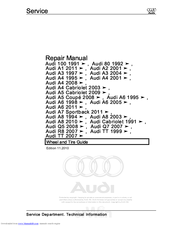
Audi A8 1994 Repair Manual (113 pages)
Wheel and Tire
Brand:
Audi
| Category:
Automobile
| Size: 2.95 MB
Table of Contents
Table of Contents
3
1 General Information
5
Wheels and Tires
5
Wheels, Tires, Wheel Alignment
5
Documents and Designations
7
Legal and Technical Requirements for Retrofitting Wheel and Tire Combinations
9
Run-Flat Tire Safety Precautions
10
Run-Flat Tire Installation Instructions
11
Additional Wheel Housing Enlargement, FLAPS
12
Rolling Resistance Tires
12
Multipart Composite Wheels
13
Wheel Bolts
13
Wheel Rims with Glued-On Wheel Trim
13
Wheel Rims, Preparing
15
Tire Requirement and Maintenance
16
Driving Style
20
Snow Chains
26
Tire Wear and Service Life
30
Tires, Rolling Noises
34
Wheels and Tires, Vibration
37
Balancing
38
Finish Balancer
42
Vehicle Pulls to One Side
46
Tire Damage
48
Impact Damage
51
Tire Pressure Monitoring System
56
Wheel Repair Kit
56
Pressure Sensor
57
Emergency Wheels
58
Tires with Emergency Running Characteristics, PAX
58
Tires with Emergency Running Characteristics, SST (Self-Supporting Tire)
65
2 Description and Operation
69
Disc Wheel Design Overview, Wheel Rims
69
Light Alloy Wheels Component Overview
71
Tires with Emergency Running Characteristics (PAX) Component Overview
73
Tire Side Wall Lettering Overview
74
Tire Pressure Monitoring System Assembly Overview
77
Fastener Tightening Specifications
79
3 Specifications
79
Wheel Bolt Tightening Specifications
79
4 Diagnosis and Testing
81
Vehicle Pulls to One Side, Correcting
81
Wheel Rotation, Non-Directional Tires
82
Wheel Rotation, Directional Tires
83
Wheels and Tires, Radial and Lateral Run Out, Checking with Tire Dial Gauge
84
Wheels and Tires, Radial and Lateral Run-Out, Checking with VAG 1435
84
Rim Radial and Lateral Run Out, Checking
85
5 Removal and Installation
87
Wheel, Changing and Mounting
87
Metal Valve Body
91
Wheel Electronics, TPMS, Beru System
96
Wheel Electronics, TPMS, Siemens System
96
Wheel Rims with Replaceable Decorative Trim, Attached with Bolts
97
Wheel Rims with Replaceable Decorative Trim, Glued
97
Tires, Changing
100
Tires, with Run-Flat Tires
102
Tires, Sealed with Sealant
106
6 Special Tools
108
Audi A8 1994 Body Repair Manual (91 pages)
Brand:
Audi
| Category:
Automobile
| Size: 2.25 MB
Table of Contents
Body Repairs
1
Table of Contents
3
Technical Data
5
Vehicle Identification Data
5
Type Plate and Vehicle Identification Number
5
Vehicle Data Sticker
5
Body - Bonded Joints
6
Body - Centre
6
Body - Rear
7
Foam-Filled Cavities
8
Corrosion Protection
10
Body Dimensions
12
Floor Group, Front
12
Floor Group, Centre
13
Floor Group, Rear
14
Body - Front
16
Body - Centre
18
Body - Rear
20
Straightening Jig
21
Body - Front
33
Wing Mounting Flange - Renewal
33
Procedure
33
Front Wheel Housing - Renewal
35
Procedure
35
Front Longitudinal Member - Renewal
38
Protected by Copyright. Copying for Private or Commercial Purposes, in Part or in Whole, Is Not
38
Procedure
38
Closure Plate for Strut Holder
41
Procedure
41
Longitudinal Member Front Section - Renewal
43
Procedure
43
Body - Centre
46
Roof - Renewal
46
Procedure
46
Pillar Trim - Renewal
49
Procedure
49
Pillar - Renewal
51
Procedure
51
Outer B-Pillar - Renewal
52
Procedure
52
Inner B-Pillar - Renewal
55
Procedure
55
Outer Side Member - Renewal
60
Procedure
60
Inner Side Member - Partial Renewal
64
Procedure
64
Top Part of Cross Panel - Renewal
68
Procedure
68
Procedure
71
Body - Rear
71
Rear Cross Panel - Renewal
71
Rear Cross Panel/Side Panel - Partial Renewal
74
Procedure
74
Luggage Compartment Floor/Side Panel - Renewal
77
Procedure
77
Rear Longitudinal Member - Partial Renewal
80
Procedure
80
Side Panel - Renewal
82
Procedure
82
Rain Channel - Renewal
89
Procedure
89
Advertisement
Related Products
Audi A8
Audi A8 292
Audi A8 2010
Audi A8 2019
Audi A8 2021
Audi A8 2016
Audi A8 2008
Audi A8 2015
Audi A8 2018
Audi A5 SPORTBACK 2009
Audi Categories
Automobile
Automobile Accessories
Engine
Car Navigation system
Car Receiver
More Audi Manuals
Login
Sign In
OR
Sign in with Facebook
Sign in with Google
Upload manual
Upload from disk
Upload from URL