Sign In
Upload
Manuals
Brands
Allied Telesis Manuals
Network Card
2911 Series
Allied Telesis 2911 Series Manuals
Manuals and User Guides for Allied Telesis 2911 Series. We have
1
Allied Telesis 2911 Series manual available for free PDF download: User Manual
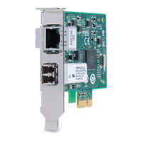
Allied Telesis 2911 Series User Manual (122 pages)
2911 Series Gigabit Ethernet Network Interface Cards
Brand:
Allied Telesis
| Category:
Network Card
| Size: 2.31 MB
Table of Contents
Radiation Exposure Statement
4
Table of Contents
7
Preface
13
Safety Symbols Used in this Document
14
Contacting Allied Telesis
15
Chapter 1: Overview
17
Physical Description
18
AT-2911 Series Single Port Adapters
18
Figure 1: AT-2911SX/SC Adapter
18
AT-2911 Series Dual Port Adapters
19
ST Fiber Optic Connector
19
Figure 2: AT-2911LTX/LC Adapter
19
Figure 3: ST Fiber Optic Connector
19
SC Fiber Optic Connector
20
LC Fiber Optic Connector
20
Twisted Pair Copper Port
20
Figure 4: SC Fiber Optic Connector
20
Figure 5: LC Fiber Optic Connector
20
Figure 6: Twisted Pair Cable Port
20
SFP Slot
21
Leds
21
Figure 7: Pin and RJ-45 Connector Pin Layout
21
Figure 8: SFP Slot
21
Table 1: LED Status
21
Model Naming Conventions
22
Figure 9: AT-2911 Model Naming Conventions
22
Table 2: AT-2911 Model Naming Conventions
22
Supported Operating Systems
23
Features
24
Broadcom Utilities
25
Teaming
25
CIM
25
Snmp
25
User Diagnostics
26
Installing Broadcom Utilities
26
Broadcom Documentation
26
Contents of Your Shipment
27
Warranty Registration
28
Chapter 2: Installing the Hardware
29
Reviewing Safety Precautions
30
Pre-Installation Checklist
32
Replacing the Bracket
33
Figure 10: Removing the Low-Profile Bracket
33
Figure 11: Fastening Screws Onto Standard Bracket
34
Installing the AT-2911 Series Adapter Card
35
Figure 12: Removing the PC Cover
35
Figure 13: Removing the Faceplate from Pcie Slot
36
Figure 14: Inserting the Network Adapter Card
37
Figure 15: Securing the Adapter Card
37
Connecting the Network Cables
39
Fiber Optic Cable
39
Table 3: 1000BASE-X Fiber Optic Cable Specifications
39
Twisted Pair Copper Cable
40
SFP Transceiver
40
Chapter 3: Modifying Advanced Properties
41
Overview
42
Guidelines
42
Twisted Pair Copper Port
42
Accessing Advanced Properties
43
Figure 16: Properties Window
43
Figure 17: Advanced Properties Window
44
Az EEE
45
Figure 18: 802.3Az EEE Page
45
ARP Offload
47
Figure 19: ARP Offload Page
47
EEE Control
48
Figure 20: EEE Control Page
48
Ethernet@Wirespeed
49
Figure 21: Ethernet@Wirespeed Page
49
Flow Control
51
Figure 22: Flow Control Page
51
Interrupt Moderation
53
Figure 23: Interrupt Moderation Page
53
Ipv4 Checksum Offload
54
Figure 24: Ipv4 Checksum Offload Page
54
Jumbo Mtu
55
Figure 25: Jumbo Mtu Page
55
Large Send Offload (Ipv4)
56
Figure 26: Large Send Offload (Ipv4) Page
56
Large Send Offload V2 (Ipv4)
58
Figure 27: Large Send Offload V2 (Ipv4) Page
58
Large Send Offload V2 (Ipv6)
60
Figure 28: Large Send Offload (Ipv6) Page
60
Network Address
61
Figure 29: Network Address Page
61
NS Offload
63
Figure 30: NS Offload Page
63
Priority & VLAN
64
Figure 31: Priority & VLAN Page
64
Receive Buffers
66
Figure 32: Receive Buffers Page
66
Receive Side Scaling
67
Figure 33: Receive Side Scaling Page
67
RSS Queues
68
Figure 34: RSS Queues Page
68
Speed & Duplex
70
Figure 35: Speed & Duplex Page
70
TCP/UDP Checksum Offload (Ipv4)
72
Figure 36: TCP/UDP Checksum Offload (Ipv4) Page
72
TCP/UDP Checksum Offload (Ipv6)
74
Figure 37: TCP/UDP Checksum Offload (Ipv6) Page
74
Virtual Machine Queues
76
Figure 38: Virtual Machine Queues Page
76
Vlan ID
77
Figure 39: VLAN ID Page
77
VMQ Lookahead Split
78
Figure 40: VMQ Lookahead Split Page
78
VMQ VLAN Filtering
79
Figure 41: VMQ VLAN Filtering Page
79
Chapter 4: Installing the Driver Software
81
Overview
82
Guidelines
82
Installing Linux Driver
82
Downloading the Driver Software
83
Figure 42: Software Downloads Search Result Example
83
Figure 43: Specifying the Folder for Unzipped Files
84
Accessing the Device Manager
85
Accessing Device Manager on Windows Server 2008 R2, Server 2008, Vista, or 7
85
Figure 44: System Window on Windows Server 2008 R2, Server 2008, Vista, and 7
85
Accessing Device Manager on Windows Server 2003 and XP
86
Figure 45: Device Manager Window on Windows Server 2008 R2, Sever 2008, Vista, and 7
86
Figure 46: System Properties Window on Windows Server 2003 and XP
87
Figure 47: Hardware Page on Windows Server 2003 and XP
87
Figure 48: Device Manager Window on Windows Server 2003 and XP
88
Installing the Driver Software
89
Installing the Driver Software on Windows Server 2008 R2, Server 2008, Vista, or 7
89
Figure 49: Ethernet Controller on Windows Server 2008 R2, Server 2008, Vista, and 7
90
Figure 50: Update Driver Software Window on Windows Server 2008 R2, Server 2008, Vista, and 7
90
Figure 51: Update Device Software Window on Windows Server 2008 R2, Server 2008, Vista, and 7
91
Installing the Driver Software on Windows Server 2003 and XP
92
Figure 52: Update Device Software Window on Windows Server 2008 R2, Server 2008, Vista, and 7
92
Figure 53: Ethernet Controller on Windows Server 2003 and XP
93
Figure 54: Hardware Update Wizard 1
93
Figure 55: Hardware Update Wizard 2
94
Figure 56: Hardware Update Wizard 3
95
Figure 57: Hardware Update Wizard 4
95
Updating the Driver Software
97
Updating the Driver on Windows Server 2008 R2, Server 2008, Vista, or 7
97
Updating the Driver on Windows Server 2003 and XP
98
Figure 58: Device Manager with an Expanded List on Windows Server 2008 R2, Server 2008, Vista and 7
98
Figure 59: Network Adapters on Windows Server 2003 & XP
99
Chapter 5: Uninstalling the Driver Software
101
Overview
102
Guidelines
102
Uninstalling the Driver Software
103
Figure 60: Confirm Device Uninstall Window
103
Chapter 6: Troubleshooting
105
Troubleshooting Checklist
106
Checking a Port LED on the Adapter
107
Testing Network Connectivity
108
Figure 61: Command Window with Ping Displayed
108
Software Problems and Solutions
109
Microsoft Remote Installation Service (RIS) Instructions
109
Windows Server 2003
109
Miscellaneous
109
Appendix A: Specifications
111
Physical and Power Specifications
112
Table 4: Physical Specifications
112
Environmental Specifications
113
Table 5: Environmental Specifications
113
Power Specifications
114
Table 6: Power Specifications
114
Performance Specification
115
Table 7: MTBF Specifications
115
Optical Specifications
116
Table 8: Optical Specifications
116
Appendix B: Cleaning Fiber Optic Connectors
117
Overview
118
Figure 62: Ferrule in an SC Connector Plug
118
Figure 63: Unclean and Clean Ferrule
118
Cleaning Fiber Optic Connectors Using a Cartridge-Type Cleaner
119
Figure 64: Cartridge Cleaner
119
Figure 65: Rubbing the Ferrule Tip on the Cleaning Surface
119
Cleaning Fiber Optic Connector Using a Swab
121
Figure 66: Lint-Free and Alcohol-Free Swabs
121
Figure 67: Cleaning a Recessed Ferrule
121
Advertisement
Advertisement
Related Products
Allied Telesis 2971 Series
Allied Telesis 2914 Series
Allied Telesis Rapier 24i
Allied Telesis Summit 24
Allied Telesis 24X
Allied Telesis 276-05
Allied Telesis 29M2/SP-BA
Allied Telesis Series
Allied Telesis 613-50550-00
Allied Telesis ADSL24A
Allied Telesis Categories
Switch
Network Router
Media Converter
Network Hardware
Wireless Access Point
More Allied Telesis Manuals
Login
Sign In
OR
Sign in with Facebook
Sign in with Google
Upload manual
Upload from disk
Upload from URL