Sign In
Upload
Manuals
Brands
Aerotech Manuals
Scanner Accessories
Nmark SSaM
Aerotech Nmark SSaM Manuals
Manuals and User Guides for Aerotech Nmark SSaM. We have
1
Aerotech Nmark SSaM manual available for free PDF download: Manual
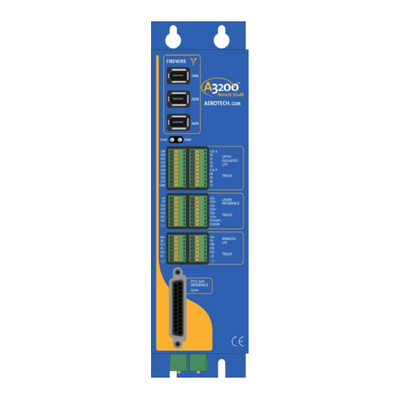
Aerotech Nmark SSaM Manual (58 pages)
Brand:
Aerotech
| Category:
Scanner Accessories
| Size: 1.67 MB
Table of Contents
Nmark Ssam Hardware Manual
1
Table of Contents
3
List of Figures
4
List of Tables
5
EU Declaration of Conformity
7
Agency Approvals
8
Safety Procedures and Warnings
9
Quick Installation Guide
11
Chapter 1: Introduction
13
Figure 1-1: Nmark Ssam Networked Digital Galvo Controller
13
Table 1-1: Feature Summary
14
Figure 1-2: Functional Diagram
15
Electrical Specifications
16
Table 1-2: Electrical Specifications
16
Figure 1-3: Dimensions
17
Mechanical Design
17
Table 1-3: Unit Weight
17
Environmental Specifications
18
Drive and Software Compatibility
19
Table 1-4: Drive and Software Compatibility
19
Chapter 2: Installation and Configuration
21
Communication Channel Settings
21
Table 2-1: Device Number Switch Settings (S2)
21
Power Connections
22
Control Supply Connections (TB109)
22
Figure 2-1: Control Supply Connections
22
Table 2-2: Control Supply Input Wiring (TB109)
22
Table 2-3: Control Supply Mating Connector (TB109)
22
Minimizing Conducted Radiated and System Noise
23
Firewire Interface
24
Table 2-4: Firewire Card Part Numbers
24
Table 2-5: Firewire Repeaters (for Cables Exceeding 4.5 M (15 Ft) Specification)
24
Table 2-6: Firewire Cables (Copper and Glass Fiber)
24
Laser Interface (TB102)
25
Table 2-7: Laser Interface Pinout (TB102 A)
25
Table 2-8: Laser Interface Pinout (TB102 B)
25
Table 2-9: Mating Connector Part Numbers for the Laser Interface Connector (TB102)
25
Figure 2-2: Laser Interface Outputs (TB102)
26
Table 2-10: Output Specifications (TB102)
26
Figure 2-3: Current Sinking Configuration (with Isolation)
27
Figure 2-4: Current Sinking Configuration (Without Isolation)
27
Figure 2-5: Current Sourcing Configuration (with Isolation)
28
Figure 2-6: Current Sourcing Configuration (Without Isolation)
28
Emergency Stop Sense Input (TB102)
29
Figure 2-7: ESTOP Sense Input (TB102)
29
Table 2-11: TB102B ESTOP Pinout
29
Table 2-12: Electrical Noise Suppression Devices
29
XY2-100 Interface (J104)
30
Table 2-13: XY2-100 Interface Connector Pinout (J104)
30
Table 2-14: Mating Connector Part Numbers for the XY2-100 Interface Connector (J104)
30
Digital Outputs (TB101 A)
31
Table 2-15: Digital Outputs Pinout (TB101 A)
31
Table 2-16: Mating Connector Part Numbers for the Digital Output Connector (TB101 A/B)
31
Table 2-17: Digital Output Specifications (TB101)
31
Figure 2-8: Digital Outputs (TB101 A)
32
Figure 2-9: Outputs Connected in Current Sourcing Mode
33
Figure 2-10: Outputs Connected in Current Sinking Mode
33
Digital Inputs (TB101 B)
34
Table 2-18: Digital Input Specifications
34
Table 2-19: Digital Inputs Pinout (TB101 B)
34
Table 2-20: Mating Connector Part Numbers for the Digital I/O Connector (TB101 A/B)
34
Figure 2-11: Digital Inputs (TB101 B)
35
Figure 2-12: Inputs Connected to a Current Sourcing Device
36
Figure 2-13: Inputs Connected to a Current Sinking Device
36
Analog I/O Interface (TB103 A/B)
37
Table 2-21: Analog I/O Pinout (TB103 A)
37
Table 2-22: Analog I/O Pinout (TB103 B)
37
Table 2-23: Mating Connector Part Numbers for the Analog I/O Connector (TB103 A/B)
37
Analog Outputs (TB103 B)
38
Figure 2-14: Analog Outputs (TB103 B)
38
Table 2-24: Analog Output Specifications (TB103 B)
38
Differential Analog Inputs (TB103 A/B)
39
Figure 2-15: Analog Inputs (TB103)
39
Table 2-25: Differential Analog Input Specifications (TB103 A/B)
39
Digital I/O Connector Interface (TB107 A/B)
40
Table 2-26: Digital Input Specifications (TB107)
40
Table 2-27: Digital Output Specifications (TB107)
40
Table 2-28: Digital I/O Pinout (TB107 A)
40
Table 2-29: Digital I/O Pinout (TB107 B)
40
Table 2-30: Mating Connector Part Numbers for the Digital I/O Connector (TB107 A/B)
40
Figure 2-16: Digital Inputs (TB107)
41
Figure 2-17: Digital Outputs (TB107)
41
Encoder Interface (TB108)
42
Table 2-31: Encoder Input Specifications (TB108)
42
Table 2-32: Axis 1 Encoder Interface Pinout (TB108A)
42
Table 2-33: Axis 2 Encoder Interface Pinout (TB108B)
42
Table 2-34: Mating Connector Part Numbers for the Encoder Connector (TB108 A/B)
42
Table 2-35: Nmark Ssam to Drive Cable Part Numbers
42
Figure 2-18: Encoder Connections (TB108 A/B)
43
Switch S1 (Laser Output Polarity/Configuration)
44
Figure 2-19: Switch S1 (Laser Output Polarity/Configuration)
44
Switch S2 (Axis Enable Polarity)
45
Figure 2-20: Switch S2 (Axis Enable Polarity)
45
PC Configuration and Operation Information
46
Chapter 3: Maintenance
47
Table 3-1: Troubleshooting
47
Test Points
48
Table 3-2: Control Board Test Points
48
Board Assembly
49
Figure 3-1: Control Board Assembly
49
Table 3-3: Control Board Jumper Selections
50
Table 3-4: Control Board Fuse Specifications
50
Preventative Maintenance
51
Table 3-5: Preventative Maintenance
51
Appendix A: Warranty and Field Service
53
Appendix B: Revision History
55
Index
57
Advertisement
Advertisement
Related Products
Aerotech NPAQ MR
Aerotech Npaq DP Series
Aerotech Ndrive ML Series
Aerotech Ndrive FCL
Aerotech Ndrive HPe 30
Aerotech Ndrive HL
Aerotech Ndrive QL
Aerotech Ndrive HPe 75
Aerotech Ndrive HPe 100
Aerotech Ndrive CL
Aerotech Categories
Industrial Equipment
DC Drives
Controller
Engine
Amplifier
More Aerotech Manuals
Login
Sign In
OR
Sign in with Facebook
Sign in with Google
Upload manual
Upload from disk
Upload from URL