Table of Contents
Advertisement
Quick Links
Advertisement
Table of Contents

Subscribe to Our Youtube Channel
Summary of Contents for Aerotech Nmark SSaM
-
Page 1: Nmark Ssam Hardware Manual
Nmark SSaM Hardware Manual Revision: 2.06.00 Patent Number: US 8,426,768 B2... - Page 2 Software Activation: The following link provides information and resources to activate your Aerotech software. Link: Software Activation Manuals, Help Files, and Cable Drawings: Browse a directory of manuals, help files, and cable drawings for Aerotech software and hardware products. Link: Browse Manuals, Help Files, and Cable Drawings Frequently Asked Questions: The Frequently Asked Questions (FAQs) section provides answers to most common questions about Aerotech products.
-
Page 3: Table Of Contents
Nmark SSaM Hardware Manual Table of Contents Table of Contents Nmark SSaM Hardware Manual Table of Contents List of Figures List of Tables EU Declaration of Conformity Agency Approvals Safety Procedures and Warnings Quick Installation Guide Chapter 1: Introduction 1.1. Electrical Specifications 1.2. -
Page 4: List Of Figures
Table of Contents Nmark SSaM Hardware Manual List of Figures Figure 1-1: Nmark SSaM Networked Digital Galvo Controller Figure 1-2: Functional Diagram Figure 1-3: Dimensions Figure 2-1: Control Supply Connections Figure 2-2: Laser Interface Outputs (TB102) Figure 2-3: Current Sinking Configuration (with Isolation) -
Page 5: List Of Tables
Table 2-33: Axis 2 Encoder Interface Pinout (TB108B) Table 2-34: Mating Connector Part Numbers for the Encoder Connector (TB108 A/B) Table 2-35: Nmark SSaM to Drive Cable Part Numbers Table 3-1: Troubleshooting Table 3-2: Control Board Test Points Table 3-3:... - Page 6 Table of Contents Nmark SSaM Hardware Manual This page intentionally left blank. www.aerotech.com...
-
Page 7: Eu Declaration Of Conformity
Nmark SSaM Hardware Manual Declaration of Conformity EU Declaration of Conformity Manufacturer Aerotech, Inc. Address 101 Zeta Drive Pittsburgh, PA 15238-2811 Product Nmark SSaM Model/Types This is to certify that the aforementioned product is in accordance with the applicable requirements of the... -
Page 8: Agency Approvals
Declaration of Conformity Nmark SSaM Hardware Manual Agency Approvals Aerotech, Inc. Model Nmark SSaM drives have been tested and found to be in accordance to the following listed Agency Approvals: Approval / Certification: CUS NRTL Approving Agency: TUV SUD America Inc. -
Page 9: Safety Procedures And Warnings
Safety Procedures and Warnings This manual tells you how to carefully and correctly use and operate the Nmark SSaM. Read all parts of this manual before you install or operate the Nmark SSaM or before you do maintenance to your system. - Page 10 Nmark SSaM Hardware Manual Electrical Safety This page intentionally left blank. www.aerotech.com...
-
Page 11: Quick Installation Guide
This chapter describes the order in which connections and settings should typically be made to the Nmark SSaM. If a custom interconnection drawing was created for your system (look for a line item on your Sales Order under the heading “Integration”), that drawing can be found on your installation device. - Page 12 Quick Installation Guide Nmark SSaM Hardware Manual This page intentionally left blank. www.aerotech.com...
-
Page 13: Chapter 1: Introduction
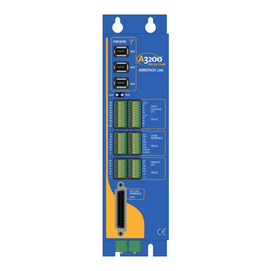
Introduction Chapter 1: Introduction Aerotech’s Nmark SSaM, part of the A3200 product family, is a galvo scanner control module that synchronizes galvo and servo motion, expanding the scanner’s field of view and broadening its application base while maintaining the high throughput capabilities expected from scanners. -
Page 14: Table 1-1: Feature Summary
Introduction Nmark SSaM Hardware Manual Table 1-1: Feature Summary Standard Features Supports 2 axis Galvo controllers via XY2-100 interface Two auxiliary channels of 40 MHz line driver quadrature encoder inputs. Eight optically-isolated digital inputs; 5-24V Eight optically-isolated digital outputs sinking or sourcing; 5-24V... -
Page 15: Figure 1-2: Functional Diagram
Nmark SSaM Hardware Manual Introduction The following block diagram shows a connection summary (refer to Chapter 2 and Chapter 3 for more detailed connection information). Figure 1-2: Functional Diagram www.aerotech.com Chapter 1... -
Page 16: Electrical Specifications
Introduction Nmark SSaM Hardware Manual 1.1. Electrical Specifications The electrical specifications for the Nmark SSaM are listed below. Table 1-2: Electrical Specifications Description Nmark SSaM Input Voltage 85-240 VAC Input Frequency 50-60 Hz Control Supply Inrush Current 16 A (peak) Input Current 0.15 A (max) -
Page 17: Mechanical Design
Nmark SSaM Hardware Manual Introduction 1.2. Mechanical Design The following figure shows the Nmark SSaM package dimension as well as the typical mounting orientation. Figure 1-3: Dimensions Table 1-3: Unit Weight Weight 1.0 kg [2.2 lb] www.aerotech.com Chapter 1... -
Page 18: Environmental Specifications
Introduction Nmark SSaM Hardware Manual 1.3. Environmental Specifications The environmental specifications for the Nmark SSaM are listed below. Operating: 0° to 50°C (32° to 122° F) Ambient Temperature Storage: -30° to 85°C (-22° to 185° F) Maximum relative humidity is 80% for temperatures up to 31°C. -
Page 19: Drive And Software Compatibility
Nmark SSaM Hardware Manual Introduction 1.4. Drive and Software Compatibility The following table lists the available drives and which version of the software first supported the drive. Drives that list a specific version number in the Last Software Version column will not be supported after the listed version. - Page 20 Introduction Nmark SSaM Hardware Manual This page intentionally left blank. Chapter 1 www.aerotech.com...
-
Page 21: Chapter 2: Installation And Configuration
Nmark SSaM is a multi-axis device, the Nmark SSaM will automatically claim the next sequential device number. If a two-axis Nmark SSaM is set to Device #2, the next drive must be set to Device #4. If a three- axis Nmark SSaM is set to Device #2, the next drive must be set to Device #5. -
Page 22: Power Connections
Installation and Configuration Nmark SSaM Hardware Manual 2.2. Power Connections The Nmark SSaM has one AC input power connector. For a complete list of electrical specifications, refer to Section 1.1. 2.2.1. Control Supply Connections (TB109) The control power supply requires a minimum of 85 VAC input to operate properly. The AC1 input is internally fused. -
Page 23: Minimizing Conducted Radiated And System Noise
The shield of the cables must be connected to the metal back shell in order for the product to conform to radiated emission standards. The Nmark SSaM is a component designed to be integrated with other electronics. EMC testing must be conducted on the final product configuration. -
Page 24: Firewire Interface
Installation and Configuration Nmark SSaM Hardware Manual 2.3. FireWire Interface The FireWire bus is the high-speed communications connection to the Nmark SSaM operating at 400 megabits per second. All command and configuration information is sent via the FireWire port. Table 2-4:... -
Page 25: Laser Interface (Tb102)
Nmark SSaM Hardware Manual Installation and Configuration 2.4. Laser Interface (TB102) The Laser Interface connector (two 8-pin, terminal block-style connectors) provides connections to the laser control outputs as well as the ESTOP sense input. There are three laser output signals and they are available in optically-isolated open drain/open source format or as RS-422 differential signals. -
Page 26: Figure 2-2: Laser Interface Outputs (Tb102)
Installation and Configuration Nmark SSaM Hardware Manual Table 2-10: Output Specifications (TB102) Specification Value Maximum Frequency (Single-Ended) 12.5 MHz Maximum Frequency (Differential) 5 MHz Voltage 5 - 24 V Output Current ≤ 50 mA Figure 2-2: Laser Interface Outputs (TB102) Chapter 2 www.aerotech.com... -
Page 27: Figure 2-3: Current Sinking Configuration (With Isolation)
Nmark SSaM Hardware Manual Installation and Configuration Figure 2-3: Current Sinking Configuration (with Isolation) Figure 2-4: Current Sinking Configuration (without Isolation) www.aerotech.com Chapter 2... -
Page 28: Figure 2-5: Current Sourcing Configuration (With Isolation)
Installation and Configuration Nmark SSaM Hardware Manual Figure 2-5: Current Sourcing Configuration (with Isolation) Figure 2-6: Current Sourcing Configuration (without Isolation) Chapter 2 www.aerotech.com... -
Page 29: Emergency Stop Sense Input (Tb102)
Nmark SSaM Hardware Manual Installation and Configuration 2.4.1. Emergency Stop Sense Input (TB102) The ESTOP sense input is used to monitor the state of an external safety circuit only. This state is indicated by the software and may be used to facilitate system restart. This ESTOP sense input is not intended to be a complete safety system. -
Page 30: Xy2-100 Interface (J104)
Installation and Configuration Nmark SSaM Hardware Manual 2.5. XY2-100 Interface (J104) The XY2-100 Interface connector (a 25-pin, D-style connector) has outputs for galvo clock, sync, and channel connections. The connector pinout is shown below. J104 is designed for a 1-to-1 connection to a galvo supporting the XY2-100 interface. -
Page 31: Digital Outputs (Tb101 A)
Nmark SSaM Hardware Manual Installation and Configuration 2.6. Digital Outputs (TB101 A) The digital outputs are optically-isolated and can be connected in sourcing or sinking configurations. The digital outputs are designed to connect to other ground referenced circuits and are not intended to provide high-voltage isolation. -
Page 32: Figure 2-8: Digital Outputs (Tb101 A)
Installation and Configuration Nmark SSaM Hardware Manual Figure 2-8: Digital Outputs (TB101 A) Chapter 2 www.aerotech.com... -
Page 33: Figure 2-9: Outputs Connected In Current Sourcing Mode
Nmark SSaM Hardware Manual Installation and Configuration Figure 2-9: Outputs Connected in Current Sourcing Mode Figure 2-10: Outputs Connected in Current Sinking Mode www.aerotech.com Chapter 2... -
Page 34: Digital Inputs (Tb101 B)
Installation and Configuration Nmark SSaM Hardware Manual 2.7. Digital Inputs (TB101 B) The digital inputs are opto-isolated and may be connected to current sourcing or current sinking devices, as shown in Figure 2-12 Figure 2-13. These inputs are designed to connect to other ground-referenced circuits and are not intended for high-voltage isolation. -
Page 35: Figure 2-11: Digital Inputs (Tb101 B)
Nmark SSaM Hardware Manual Installation and Configuration Figure 2-11: Digital Inputs (TB101 B) www.aerotech.com Chapter 2... -
Page 36: Figure 2-12: Inputs Connected To A Current Sourcing Device
Installation and Configuration Nmark SSaM Hardware Manual Figure 2-12: Inputs Connected to a Current Sourcing Device Figure 2-13: Inputs Connected to a Current Sinking Device Chapter 2 www.aerotech.com... -
Page 37: Analog I/O Interface (Tb103 A/B)
Nmark SSaM Hardware Manual Installation and Configuration 2.8. Analog I/O Interface (TB103 A/B) This connector has four differential analog inputs and three analog outputs. Table 2-21: Analog I/O Pinout (TB103 A) Label Description In/Out/Bi Connector Analog Input 0+ Input Analog Input 0-... -
Page 38: Analog Outputs (Tb103 B)
Installation and Configuration Nmark SSaM Hardware Manual 2.8.1. Analog Outputs (TB103 B) The analog output is set to zero when power is first applied to the system or during a system reset. Table 2-24: Analog Output Specifications (TB103 B) Specification... -
Page 39: Differential Analog Inputs (Tb103 A/B)
Nmark SSaM Hardware Manual Installation and Configuration 2.8.2. Differential Analog Inputs (TB103 A/B) To interface to a single-ended (non-differential) voltage source, connect the signal common of the source to the negative input and the analog source signal to the positive input. A floating signal source should be... -
Page 40: Digital I/O Connector Interface (Tb107 A/B)
Installation and Configuration Nmark SSaM Hardware Manual 2.9. Digital I/O Connector Interface (TB107 A/B) The digital I/O connector provides eight non-isolated inputs and two non-isolated outputs. The inputs are filtered and connected to a 74LCX16244 (Figure 2-16). The two outputs are driven by 74AHCT1G14 inverters (Figure 2-17). -
Page 41: Figure 2-16: Digital Inputs (Tb107)
Nmark SSaM Hardware Manual Installation and Configuration Figure 2-16: Digital Inputs (TB107) Figure 2-17: Digital Outputs (TB107) www.aerotech.com Chapter 2... -
Page 42: Encoder Interface (Tb108)
Installation and Configuration Nmark SSaM Hardware Manual 2.10. Encoder Interface (TB108) The Nmark SSaM is equipped with two auxiliary encoder input channels that are accessible through TB108A/B. The encoder interfaces accept an RS-422 differential line driver. Table 2-31: Encoder Input Specifications (TB108) -
Page 43: Figure 2-18: Encoder Connections (Tb108 A/B)
Nmark SSaM Hardware Manual Installation and Configuration Figure 2-18: Encoder Connections (TB108 A/B) www.aerotech.com Chapter 2... -
Page 44: Switch S1 (Laser Output Polarity/Configuration)
Installation and Configuration Nmark SSaM Hardware Manual 2.11. Switch S1 (Laser Output Polarity/Configuration) Define the active laser output polarity using the Laser Output Polarity switches of S1 (see Section 2.4.). The CONFIG switch sets the Nmark to two or three axis mode (OFF= two axis, ON= three axis). -
Page 45: Switch S2 (Axis Enable Polarity)
Nmark SSaM Hardware Manual Installation and Configuration 2.12. Switch S2 (Axis Enable Polarity) The axis enable polarity switches are currently not used. Figure 2-20: Switch S2 (Axis Enable Polarity) www.aerotech.com Chapter 2... -
Page 46: Pc Configuration And Operation Information
Installation and Configuration Nmark SSaM Hardware Manual 2.13. PC Configuration and Operation Information For additional information about PC configuration, hardware requirements, programming, utilities, and system operation refer to the A3200 Help file. Chapter 2 www.aerotech.com... -
Page 47: Chapter 3: Maintenance
Chapter 3: Maintenance This section covers the internal boards, important board components, and how to clean the drive. D A N G E R : Always disconnect the Mains power connection before opening the Nmark SSaM chassis. D A N G E R : Before performing any tests, be aware of lethal voltages inside the controller and at the input and output power connections. -
Page 48: Test Points
3.1. Test Points The following test points are available internally to the Nmark, refer to Section 3.2. for their locations. All test points not shown are for Aerotech internal use only. Table 3-2: Control Board Test Points Test Point Description Test Point... -
Page 49: Board Assembly
Table 3-3 lists the jumpers and the default configurations for the Nmark board. D A N G E R : Always disconnect the Mains power connection before opening the Nmark SSaM chassis. Figure 3-1: Control Board Assembly www.aerotech.com... -
Page 50: Table 3-3: Control Board Jumper Selections
Troubleshooting Nmark SSaM Hardware Manual Table 3-3: Control Board Jumper Selections Jumpers Positions Function Laser Output 3 (O3) Sinking JP4-JP5 Laser Output 3 (O3) Sourcing Laser Output 2 (O2) Sinking JP6-JP7 Laser Output 2 (O2) Sourcing Laser Output 1 (O1) Sinking... -
Page 51: Preventative Maintenance
Cleaning The Nmark SSaM chassis can be wiped with a clean, dry, soft cloth. The cloth may be slightly moistened if required with water or isopropyl alcohol to aid in cleaning if necessary. In this case, be careful not to allow moisture to enter the Nmark SSaM or onto exposed connectors / components. - Page 52 Troubleshooting Nmark SSaM Hardware Manual This page intentionally left blank. Chapter 5 www.aerotech.com...
-
Page 53: Appendix A: Warranty And Field Service
Aerotech makes no warranty that its products are fit for the use or purpose to which they may be put by the buyer, whether or not such use or purpose has been disclosed to Aerotech in specifications or drawings previously or subsequently provided, or whether or not Aerotech’s... - Page 54 Aerotech's approval. On-site Warranty Repair If an Aerotech product cannot be made functional by telephone assistance or by sending and having the customer install replacement parts, and cannot be returned to the Aerotech service center for repair, and if Aerotech determines the problem could be warranty-related, then the following policy applies:...
-
Page 55: Appendix B: Revision History
Nmark SSaM Hardware Manual Revision History Appendix B: Revision History Revision Description Updated EU Declaration of Conformity 2.06.00 Added cable part numbers: Section 2.10. Encoder Interface (TB108) The following sections have been modified: EU Declaration of Conformity Agency Approvals 2.05.00 Section 2.7. - Page 56 Revision History Nmark SSaM Hardware Manual This page intentionally left blank. Appendix B www.aerotech.com...
-
Page 57: Index
Nmark SSaM Hardware Manual Index Index FireWire Cables FireWire Card Part Numbers 2014/35/EU FireWire Interface FireWire Repeaters Altitude Functional Diagram Ambient Temperature Axis Enable Polarity Global Technical Support Board Assembly Humidity Check chassis for loose or damaged parts / Inputs Connected to a Current Sinking Device... - Page 58 Index Nmark SSaM Hardware Manual 21,45 Standard Features Support Switch S2 (Axis Enable Polarity) TB101 A TB101 B TB102 25,29 TB103 37,39 TB107 TB108 TB109 Technical Support Test Points unit weight XY2-100 Interface (J104) Index www.aerotech.com...
Need help?
Do you have a question about the Nmark SSaM and is the answer not in the manual?
Questions and answers