Sign In
Upload
Manuals
Brands
ADEMCO Manuals
Security System
N7227V5
ADEMCO N7227V5 Manuals
Manuals and User Guides for ADEMCO N7227V5. We have
2
ADEMCO N7227V5 manuals available for free PDF download: Installation And Setup Manual, Installation Instructions Manual
ADEMCO N7227V5 Installation Instructions Manual (88 pages)
Vista user guide security camera N7227V5
Brand:
ADEMCO
| Category:
Security System
| Size: 1.5 MB
Table of Contents
Table of Contents
3
How to Use this Manual
7
Conventions Used in this Manual
8
Section 1. GENERAL DESCRIPTION
9
Figure 1. Installing the Cabinet Lock
11
Section 2. INSTALLING the CONTROL
11
Installing the Control's Circuit Board Alone or (if Used), with a 4204 Relay Unit
11
Installing the Lock (if Used)
11
Mounting the Cabinet
11
Figure 3. Installing the PC Board & RF Receiver Together in the Cabinet
12
Figure 4. Standard Telephone Line Connections
13
Earth Ground Connections
14
Installing the Back-Up Battery
14
Wiring the AC Transformer
14
Figure 2. Installing the PC Board Alone, or (if Used), with a 4204 Relay Unit
12
Installing Control and RF Receiver Circuit Boards Together in the Cabinet
13
Standard Phone Line Connections
13
Section 3. INSTALLING REMOTE KEYPADS
15
Keypads that May be Used
15
Wiring to the Keypads
15
Wiring Run Chart for Devices Drawing AUX Power from the Control
15
Figure 5. Keypad Connections to the Control Board
16
Mounting the Keypads
16
Using a Supplementary Power Supply to Power Additional Keypads
16
Figure 6. Using a Supplementary Power Supply for Keypads
17
Preliminary Check-Out Procedure
17
Figure 7. 4-Wire Smoke Detector Connections to Zone 5
18
Compatible 4-Wire Smoke/Combustion Detectors
19
Programming Hard-Wired Zones
19
Programming Panic Keys
20
Check-Out Procedure for Hard-Wired Zones 1-6
21
Basic Hard-Wired Zones 1-6
18
Installing the Hard-Wired Zones
18
Common Characteristics for Zones 1-6
18
Wiring Burglary and Panic Devices to Zones 1-6
18
Wiring 4-Wire Smoke/Combustion Detectors on Zones 5
18
Wireless (Rf) Zone Expansion (5700 & 5800 Rf Systems)
22
Section 5. WIRELESS (RF) ZONE EXPANSION (5700 & 5800 RF SYSTEMS)
22
Wireless System Operation and Transmitter Supervision
22
Transmitter Battery Life
23
Wireless Systems Available
22
Installation and Setup of the 4281/5881 Series Wireless Receivers
23
Receiver Supervision
23
5700 Series Transmitter Setup
24
Figure 8. 4281, 5881, and 5882 Wireless Receivers (Cover Removed)
24
Installing the 5800TM Module
24
Setting the DIP Switches on 5700 Series Wireless Transmitters
25
Wireless Zone/ID Assignments for 5700 Series Transmitters
25
DIP Switch Tables for 5700 RF System Wireless Devices
26
Compatible 5700 Series Transmitters
27
Programming the Control for a 5700 Wireless System
28
Using the House ID Sniffer Mode (5700 Systems)
28
Zone Programming for 5700 Series Transmitters
28
Go/Nogo Test
30
5800 Series Transmitter Setup
31
5800 Series Transmitter Input Loops
31
5800 Series Transmitter Input Types
31
Compatible 5800 Series Transmitters
32
Programming the RF Transmitters (5800 RF Systems)
33
Enrolling 5800 Transmitters into the System
34
Enrolling through Zone Programming ( 56)
34
Check-Out Procedure for Wireless Zones
37
Transmitter ID Sniffer Mode (5700 RF Systems Only)
37
Go/No Go Test Mode (5700 and 5800 RF Systems)
37
Deleting a Transmitter Serial Number from a Zone in 56 Mode (5800 System)
37
To Either Temporarily or Permanently Remove a Zone from the System (5800 System)
37
4204 Relay Modules
39
4204 Setup
39
Supervision
39
Section 6. RELAY OUTPUT DEVICES
39
Figure 9. 4204 Connections to Control
39
Programming Options Defined
39
Relay Device Basics
39
Programming Output Relays
41
Example of Output Relay Programming
43
4285 Phone Module
44
Installing the Phone Module
44
General Information
44
Mounting the Phone Module
44
Phone Module Wiring
44
Caller ID Units
45
Figure 10. 4285 Phone Module Wiring Connections
46
Programming the Control for Phone Access
47
Checking the Operation of the 4285 Phone Module
48
Section 8. EXTERNAL SOUNDERS
49
Compatible Sounders
49
Sounder Connections
50
Programming for External Sounders
50
Testing the Sounder
50
Figure 11. Typical Sounder Wiring
50
Figure 12. Long Range Radio Connections
51
Section 9. LONG RANGE RADIO
51
General Information
51
Connection
51
Programming for Long Range Radio
51
Audio Alarm Verification (Aav) Unit
52
General Information
52
Wiring Connections
52
Programming
52
Figure 13. Connection of AAV Unit When Not Using a 4285 Phone Module
53
Figure 14. Connection of AAV Unit When also Using a 4285 Phone Module
53
Section 11. FINAL POWER up
54
Earth Ground Connections
54
AC Power-Up
54
Connecting the Back-Up Battery
54
Calculating the Battery Size Needed
54
Making the Battery Connections
55
Auxiliary Device Current Draw Worksheet
55
Alpha Descriptor Programming
56
Assigning Zone Descriptors
56
Entering Zone Descriptors (in Program Menu Mode 82)
56
Programming the Descriptors
56
Section 12. ALPHA DESCRIPTOR PROGRAMMING
56
Alternate Method for Programming Zone Descriptors
58
Adding Custom Words
59
Alpha Vocabulary List (for Entering Zone Descriptors)
60
Character (ASCII) Chart
60
Sequential Mode
61
(For 5800 Series Wireless Transmitters)
61
Section 14. SYSTEM COMMUNICATION
64
Report Code Formats
64
Table of Contact ID Event Codes
66
Communication Programming
66
Section 15. TESTING the SYSTEM
71
Test Procedure
71
To the Installer
72
Section 16. SYSTEM OPERATION
73
Security Codes
73
Installer Code
73
Assigning the Master Code
73
Changing the Master Code
73
User Codes
73
Duress Code
73
Keypad Functions
74
General Information
74
Arming Functions
74
Panic Keys
75
4285 Phone Module (if Used)
75
Relays Outputs (if Used)
75
Exit Alarm Displays (if Programmed)
75
Trouble Conditions
76
General Information
76
Check" and "Battery" Displays
76
Power Failure
76
Other Displays
76
Section 17. TROUBLESHOOTING GUIDE
77
Contacting Technical Support
79
Section 18. SPECIFICATIONS & ACCESSORIES
80
Specifications
80
Accessories (Compatible Devices)
82
Regulatory Agency Statements
83
Limitations of this Alarm System
86
Summary of Connections Diagram
88
Limited Warranty
88
Advertisement
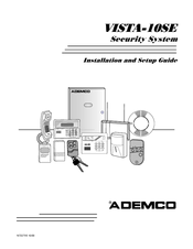
ADEMCO N7227V5 Installation And Setup Manual (100 pages)
Vista Security System Installation and Setup Guide
Brand:
ADEMCO
| Category:
Security System
| Size: 0.65 MB
Table of Contents
Recommendations for Proper Protection
2
Table of Contents
3
Introduction
5
Description
5
Features
5
Installing the Control
9
Mounting the Cabinet
9
Installing the Lock (if Used)
9
Mounting the Control's Circuit Board Alone in the Cabinet
10
Standard Phone Line Connections
11
SECTION 3. Installing Remote Keypads
13
Keypads that May be Used
13
Wiring to the Keypads
13
Mounting the Keypads
14
Supplementary Power for Additional Keypads
14
Preliminary Checkout Procedure
15
Basic Hardwired Zones 1-6
17
Installing the Hardwired Zones
17
Programming Hardwired Zones
18
Wireless Expansion (5800 System)
19
About Wireless Expansion
19
Installing the 5881/5882 Receiver
20
Installing the 5800TM Module
21
About Jam Detection and Reporting
21
5800 Series Transmitters
21
Series Transmitters Table
23
Installing 5800 Series Transmitters
24
Relay Output Devices
25
Relay Device Basics
25
4204 Relay Modules
25
Programming Options
26
4285 And 4286 VIP Module
27
Installing the (Voice Interactive Phone) Module
27
Programming the Control for Phone Access
30
Checking the Operation of the VIP Module
30
External Sounders
31
Compatible Sounders
31
Nfpa Requirements
31
Sounder Connections and Power
32
Sounder Supervision
32
Testing the Sounder
32
Long-Range Radio
33
About Long-Range Radio
33
Programming for Long-Range Radio
33
Dynamic Signaling Feature
34
SECTION 10. Audio Alarm Verification (AAV) Unit
35
About Audio Alarm Verification
35
SECTION 11. Final Power-Up
37
Earth Ground Connections
37
Wiring the AC Transformer
37
AC Power-Up
38
Calculating the Battery Size Needed
38
Connecting the Backup Battery
39
SECTION 12. Mechanics of Programming
41
About Programming
41
Entering the Program Mode
41
SECTION 13. Zone Response Type Definitions
43
Zone Type Definitions
43
SECTION 14. Data Field Descriptions
47
Descriptions of System Data Fields
47
SECTION 15. Zone Programming
57
About Zone Programming
57
Series Transmitter Input Loop Identification
60
SECTION 16. Output Device Programming
69
Programming Options Defined
69
SECTION 17. Zone Lists
73
About Zone List Menu Mode
73
Zone List Displays
73
SECTION 18. Alpha Descriptor Programming
75
About Alpha Descriptor Programming
75
Zone Descriptors
75
SECTION 19. Remote Programming and Control (Downloading)
81
SECTION 20. System Communication
83
Panel Communication with Central Station
83
Report Code Formats
83
Table of Contact ID Event Codes
84
SECTION 21. System Operation
85
Security Codes
85
Keypad Functions
86
Trouble Conditions
88
SECTION 22. Testing the System
91
Test Procedure
91
SECTION 23. Specifications & Accessories
93
Specifications
93
Accessories (Compatible Devices)
94
Appendix A Regulatory Agency Statements
95
APPENDIX B Limitations and Warranties
97
Advertisement
Related Products
ADEMCO Ademco N7001V2
ADEMCO 1021
ADEMCO 4021
ADEMCO 4080
ADEMCO 4080-12
ADEMCO 4080XL
ADEMCO 4110
Ademco 4110DL
ADEMCO Categories
Security System
Security Sensors
Keypad
Transmitter
Smoke Alarm
More ADEMCO Manuals
Login
Sign In
OR
Sign in with Facebook
Sign in with Google
Upload manual
Upload from disk
Upload from URL