Sign In
Upload
Manuals
Brands
ABB Manuals
Measuring Instruments
FSM4000-SE41F
ABB FSM4000-SE41F Manuals
Manuals and User Guides for ABB FSM4000-SE41F. We have
2
ABB FSM4000-SE41F manuals available for free PDF download: Operating Instruction, Commissioning Instruction
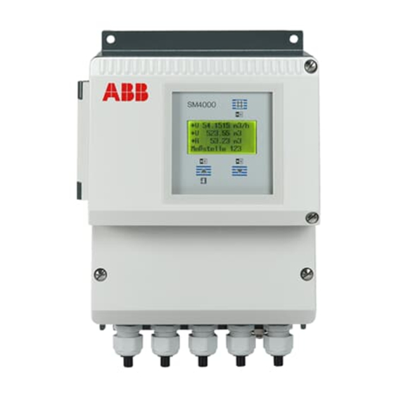
ABB FSM4000-SE41F Operating Instruction (128 pages)
Electromagnetic Flowmeter
Brand:
ABB
| Category:
Measuring Instruments
| Size: 2.97 MB
Table of Contents
Dransfelder Straße
2
Table of Contents
3
1 Safety
6
General Information and Notes for the Reader
6
Intended Use
7
Improper Use
7
Target Groups and Qualifications
7
Warranty Provisions
7
Safety-/ Warning Symbols, Note Symbols
8
Name Plate / Factory Tag
9
Germany
10
Germany
11
Transport Safety Information
12
Installation Safety Information
12
Electrical Installation Safety Information
12
Safety Instructions for Operation
13
Technical Limit Values
13
Allowed Fluids
13
Maintenance and Inspection Safety Information
14
Returning Devices
14
Integrated Management System
15
Disposal
15
Information on WEEE Directive 2012/19/EU (Waste Electrical and Electronic Equipment)
15
2 Design and Function
16
Measuring Principle
16
Design
17
Device Designs
17
3 Transport
18
Inspection
18
General Information on Transport
18
Transport of Flanged Units up to Nominal Diameter DN 300
18
Transport of Flanged Units Larger than Nominal Diameter DN 350
19
4 Mounting
20
General Information on Installation
20
Supports for Nominal Diameters Larger than DN 350
20
Mounting the Meter Tube
21
Torque Information
22
Flanged Units and Units with Adapter Flange, Model SE41F / SE21F / SE21W
22
Variable Process Connections Model SE21
25
Information on 3A Conformity
26
Installation Requirements
27
Electrode Axis
27
In- and Outlet Pipe Sections
27
Vertical Connections
27
Horizontal Connections
27
Free Inlet or Outlet
27
Strongly Contaminated Fluids
27
Installation in the Vicinity of Pumps
28
Installing the High Temperature Design
28
Installation in Pipelines with Larger Nominal Diameter
28
Flowmeter Sizes, Pressure Ratings, Flow Range
29
Ground
30
General Information on Ground Connections
30
Metal Pipe with Fixed Flanges
30
Metal Pipe with Loose Flanges
31
Non-Metallic Pipes or Pipes with Insulating Liner
31
Flowmeter Sensor in Stainless Steel Design Model SE21
32
Ground for Devices with Protective Plates
32
Ground with Conductive PTFE Grounding Plate
32
5 Electrical Connections
33
Preparing and Routing the Signal and Magnet Coil Cable
33
Connecting the Flowmeter Sensor
35
Connecting the Signal and Magnet Coil Cables
35
Protection Class IP 68
36
Connecting the Transmitter
38
Supply Power Connection
38
Connecting the Signal and Magnet Coil Cables
39
Terminal Connection Diagrams
40
Connection Examples for Peripherals (Incl. HART)
44
6 Commissioning
47
Preliminary Checks Prior to Start-Up
47
Commissioning the Unit
49
Switching on Supply Power
49
Device Configuration
49
Easy Set-Up: for Uncomplicated Configuration
51
Commissioning PROFIBUS PA Units
52
Information on Voltage/Current Consumption
54
System Integration
55
Commissioning FOUNDATION Fieldbus Units
56
7 Parameterization
58
Display Options
58
Data Entry
59
Entering Data in "Short Form
61
Additional Information Regarding Use of Enhanced Diagnostic Functions
88
Determining Measurement Values for Diagnostics
88
Recommended Settings for Diagnostic Limit Values
92
Displaying the Diagnostic Values
94
Readjusting the Coil Temperature
97
Software History
98
For Transmitters Without Communication or HART Protocol
98
For Transmitter with PROFIBUS PA Communication
99
For Transmitter with FOUNDATION Fieldbus Communication
99
8 Messages and Tests
100
Overview of Error States and Alarms
100
Error Messages During Operation and with Data Entry
101
Warning Messages During Operation
103
9 Maintenance / Repair
105
Flowmeter Sensor
105
Gaskets
105
Replacing the Transmitter
106
10 Spare Parts List
108
Fuses for Transmitter Electronics
108
Spare Parts for Transmitter S4
109
Field Housing Unit
109
Spare Parts Flowmeter Sensor
110
Terminal Box, Stainless Steel, DN 1
110
Terminal Box, Aluminum, DN 3
111
11 Operating S4 with an Older Sensor
112
12 Specifications
115
Measuring Accuracy
115
Reference Conditionsper en 29104
115
Maximum Measuring Error
115
Flowmeter Sensor
116
Flowmeter Sensor SE41F
116
Flowmeter Sensor SE21 / SE21F
119
Transmitter S4
121
13 Appendix
122
Other Applicable Documents
122
Approvals and Certifications
122
Overview of Setting Parameters and Technical Design
123
Return Form
124
Germany
128
Advertisement
ABB FSM4000-SE41F Commissioning Instruction (50 pages)
Brand:
ABB
| Category:
Measuring Instruments
| Size: 1.43 MB
Table of Contents
Table of Contents
4
1 Safety
6
General Safety Information
6
Intended Use
6
Improper Use
6
Technical Limit Values
7
Allowed Fluids
7
Symbols and Warnings
8
Operator Liability
8
Personnel Qualification
8
Transport Safety Information
8
1.10 Installation Safety Information
9
1.11 Electrical Installation Safety Information
9
1.12 Operating Safety Information
10
1.13 Maintenance and Inspection Safety Information
10
2 Transport
11
Inspection
11
General Information on Transport
11
Transport of Flanged Units Smaller than DN 350
11
Transport of Flanged Units Larger than DN 300
11
3 Installation
12
General Information on Installation
12
Supports for Meter Sizes Larger than DN 300
12
Mounting the Meter Tube
13
Torque Information
14
Flanged Flowmeter Model SE41F/SE21F / Wafer Flange Unit Model SE21W
14
Variable Process Connections Model SE21
14
Information on 3A Conformity
15
Installation Requirements
16
Electrode Axis
16
In- and Outlet Pipe Sections
16
Vertical Connections
16
Horizontal Connections
16
Free Inlet or Outlet
16
Strongly Contaminated Fluids
16
Installation in the Vicinity of Pumps
17
Ground
17
General Information on Ground Connections
17
Metal Pipe with Fixed Flanges
17
Metal Pipe with Loose Flanges
18
Non-Metallic Pipes or Pipes with Insulating Liner
18
Flowmeter Sensor in Stainless Steel Design Model SE21
18
Ground for Devices with Hard Rubber Lining
18
Ground for Devices with Protective Plates
18
Ground with Conductive PTFE Grounding Plate
18
4 Electrical Connection
19
Preparing and Routing the Signal and Magnet Coil Cable
19
Connecting the Flowmeter Sensor
21
Connecting the Signal and Magnet Coil Cables
21
Protection Class IP 68
22
Installing the High Temperature Design
24
Terminal Connection Diagrams
25
Connection Examples for Peripherals (Incl. HART)
28
5 Startup Operation
30
Preliminary Checks Prior to Start-Up
30
Switching on Supply Power
31
Commissioning PROFIBUS PA Units
32
Information on Voltage/Current Consumption
34
System Integration
34
Commissioning FOUNDATION Fieldbus Units
35
6 Parameterization
37
Data Entry
37
Entering Data in "Short Form
39
Easy Set-Up: for Uncomplicated Configuration
40
7 Messages and Tests
41
Error Messages During Operation and with Data Entry
41
Warning Messages During Operation
43
8 Appendix
45
Additional Documents
45
Permits and Certifications
45
D184B141U02 Fsm4000 en
47
Advertisement
Related Products
ABB FSM4000 Series
ABB FSM4000-SE21
ABB FSM4000-SE21F
ABB FSM4000-S4
ABB FSM4000-SE21W
ABB FS4000
ABB VortexMaster FSV450
ABB FS4000-ST4
ABB FS4000-SR4
ABB SwirlMaster FSS450
ABB Categories
Industrial Equipment
Controller
Measuring Instruments
Battery Charger
DC Drives
More ABB Manuals
Login
Sign In
OR
Sign in with Facebook
Sign in with Google
Upload manual
Upload from disk
Upload from URL